|
|
Last updated: 2021/04/27 Page Index
The ARGUS vacuum tube television (not my build)
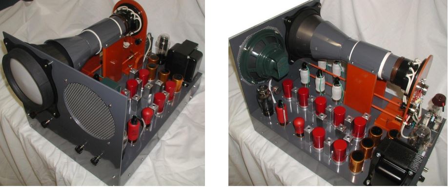
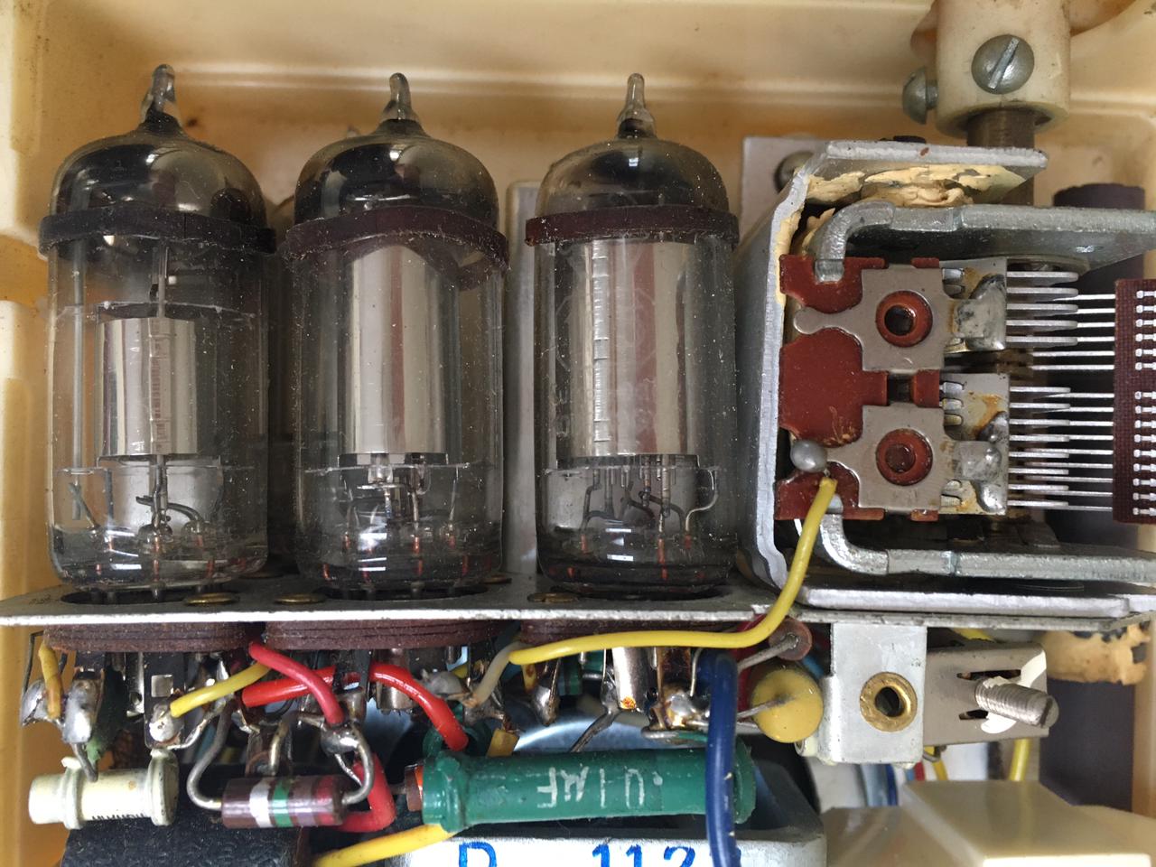
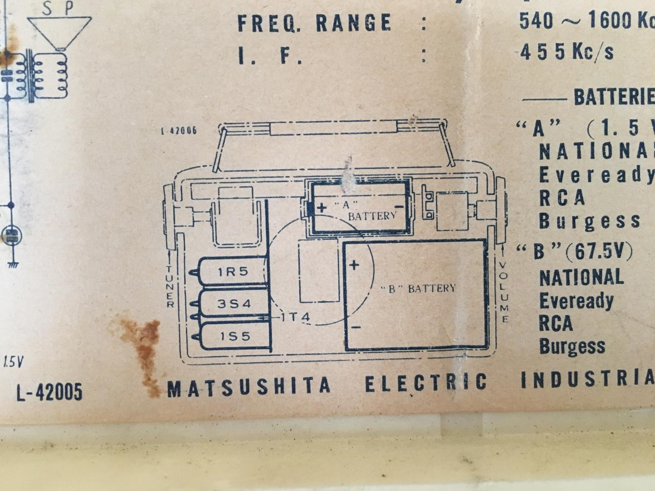
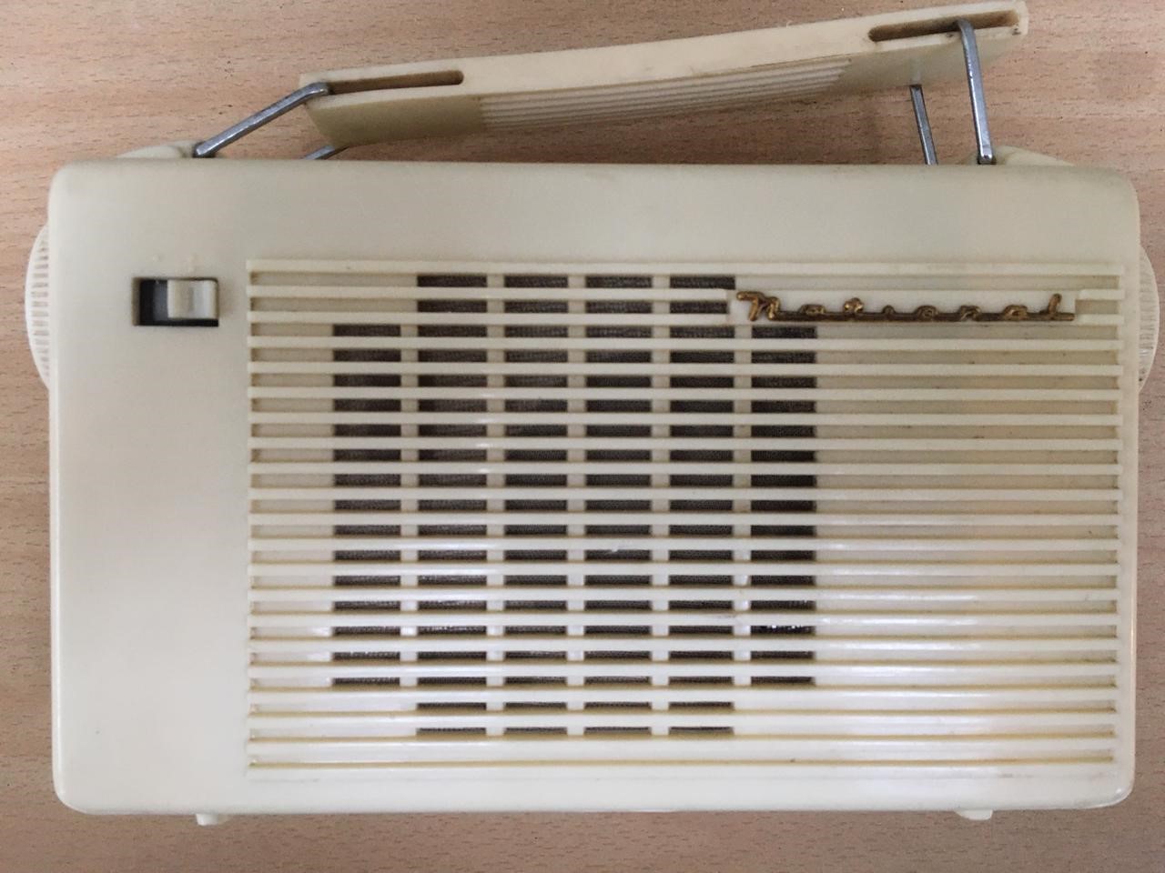
National Portable Tube Radio Model PL-420A and PL-420B Second pulse counting FM radio 24 December 2014
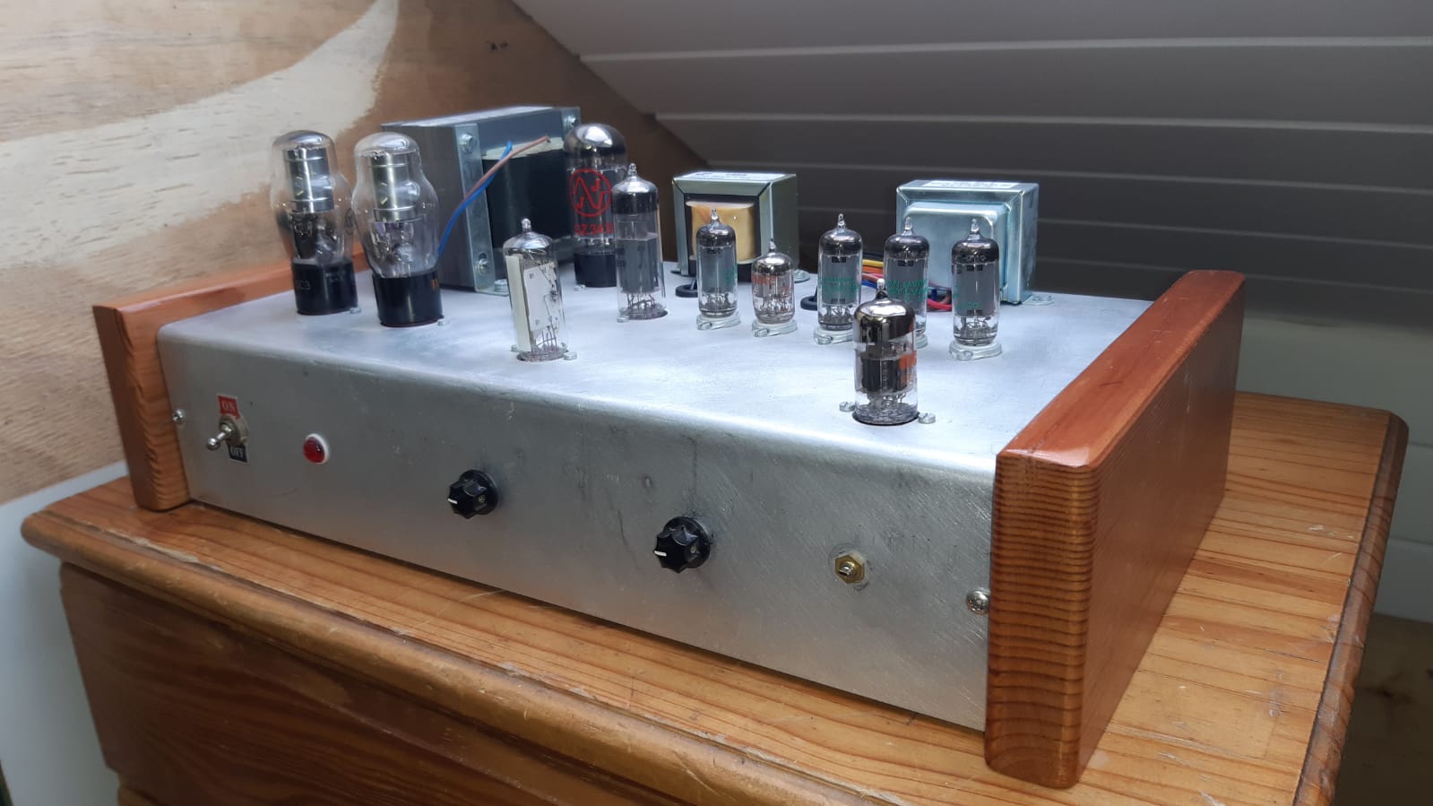
I gave the radio away to a fellow vintage technology enthusiast, Paul. He put these lovely side panels on the set. Very nice!
This is the second FM radio I built. As before the design is by John in Australia. The design is similar to the previous one. A 6BL8 local oscillator heterodynes the tuned channel down to an IF of about 150kHz. This radio has a greater audio output thanks to the 6AU6 and the 6BM8. My radio uses a Russian made 6F3P equivalent tube which is actually a beam tetrode and not a pentode. It works exactly the same though as the 6BM8. As I understand it, only the Mullard ECL82 used the pentode configuration. The radio frequency chokes are the hand made versions John recommends.
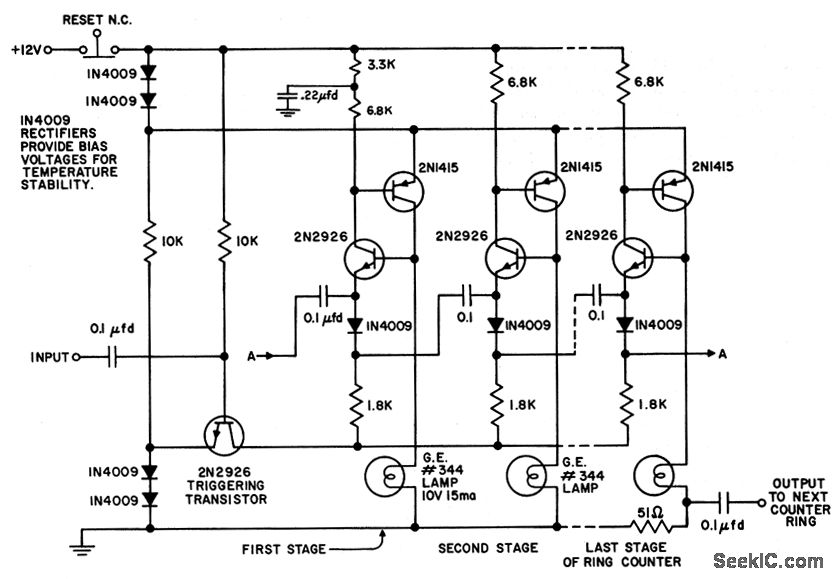
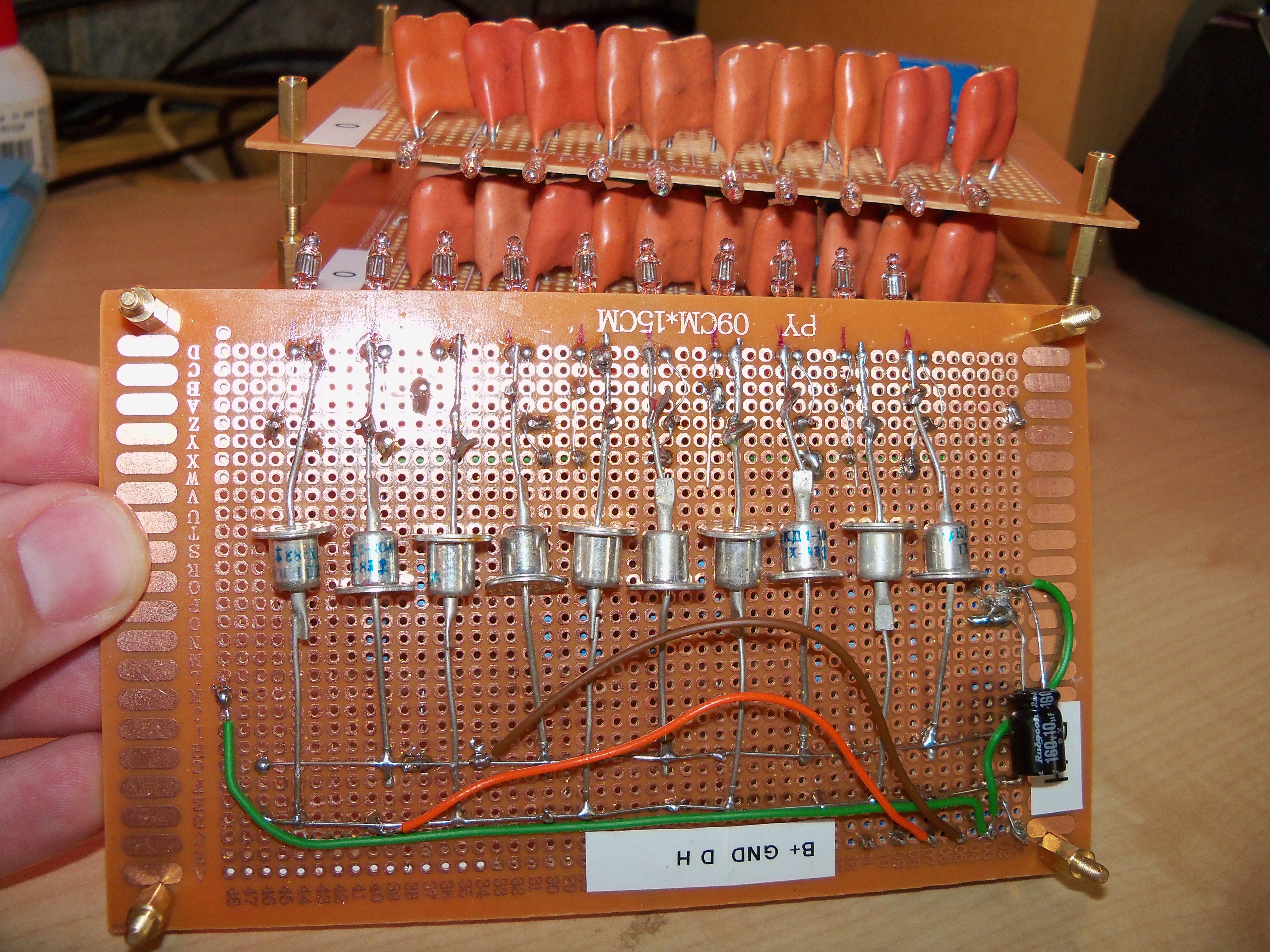
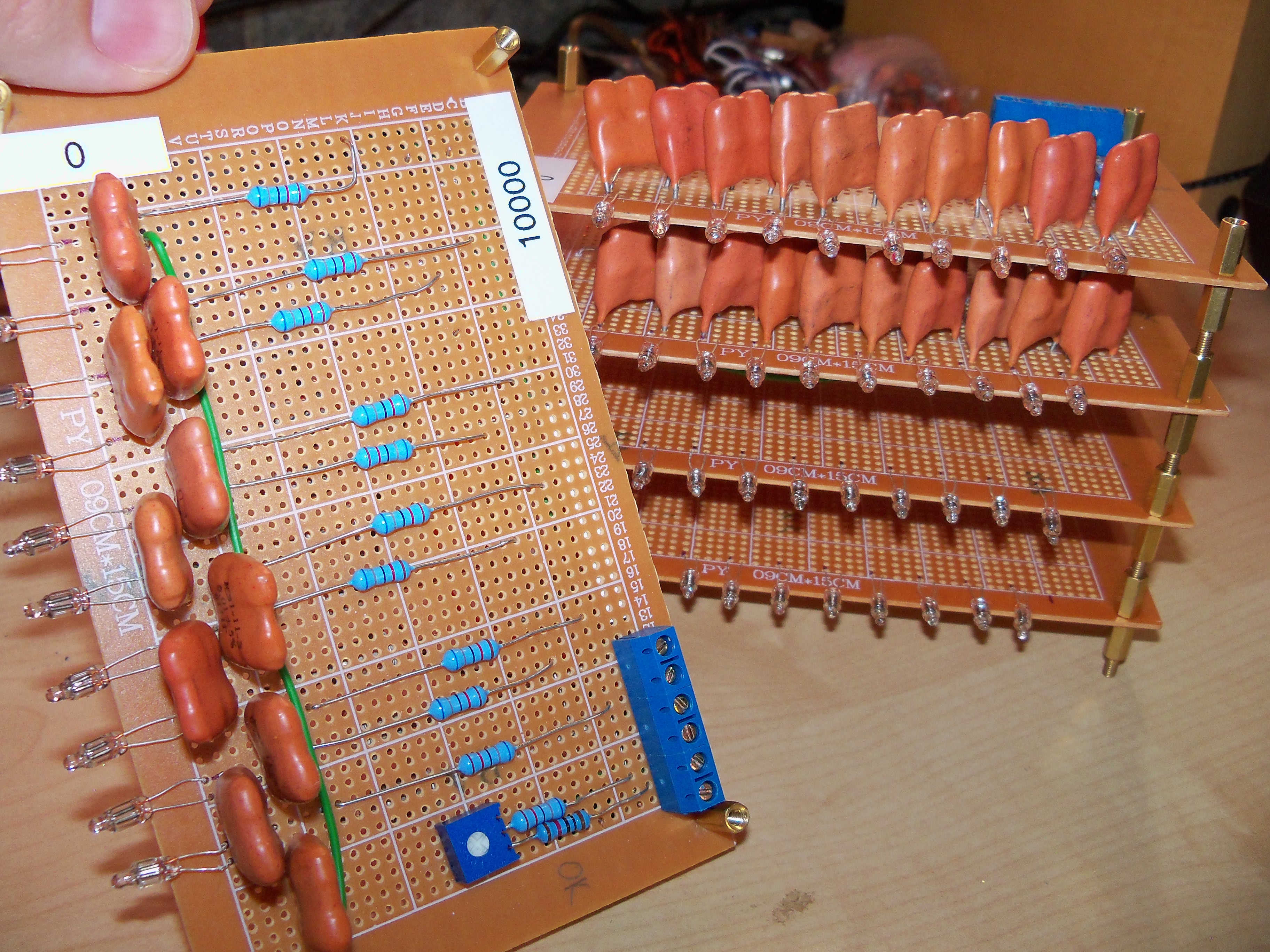
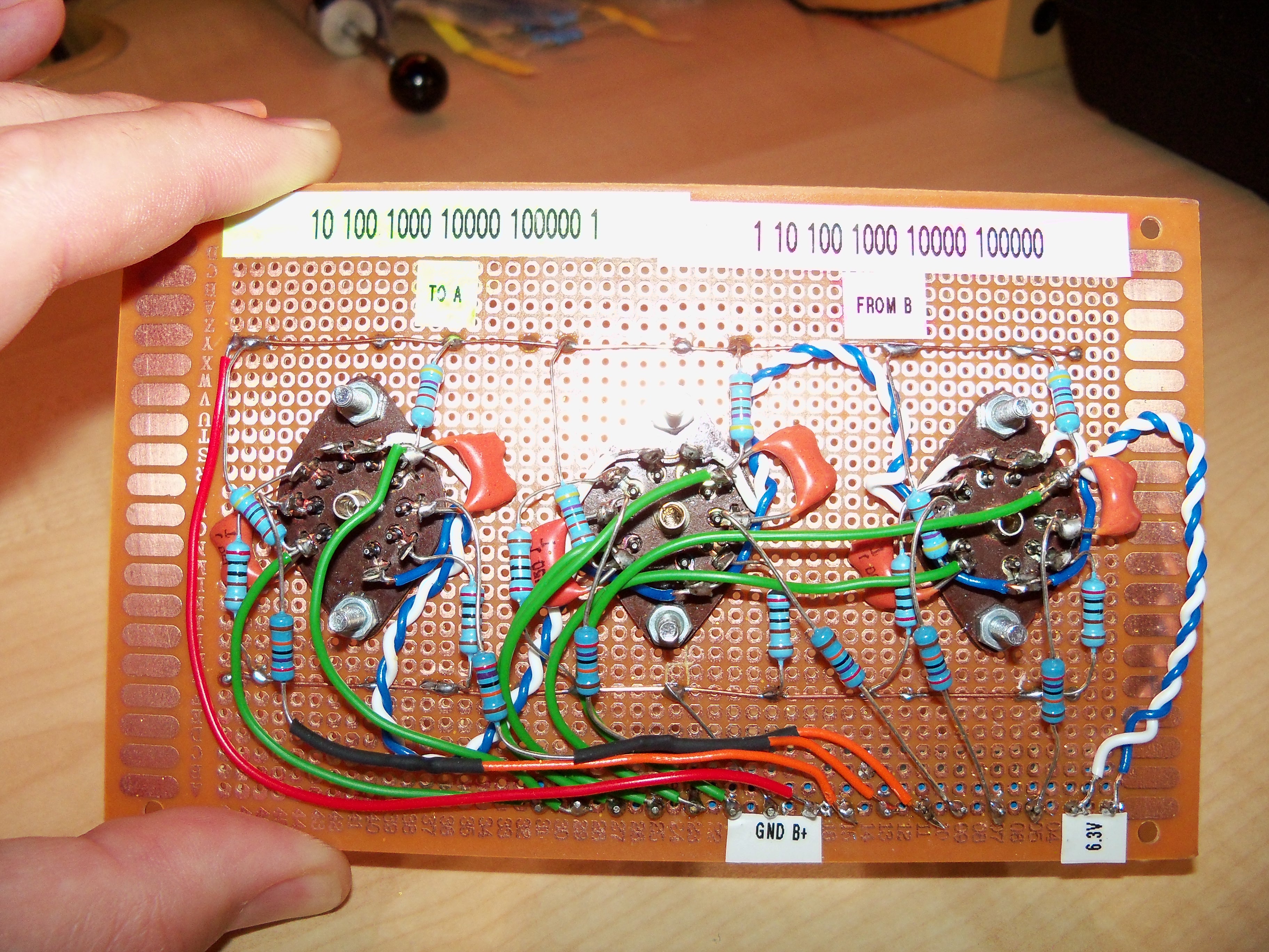
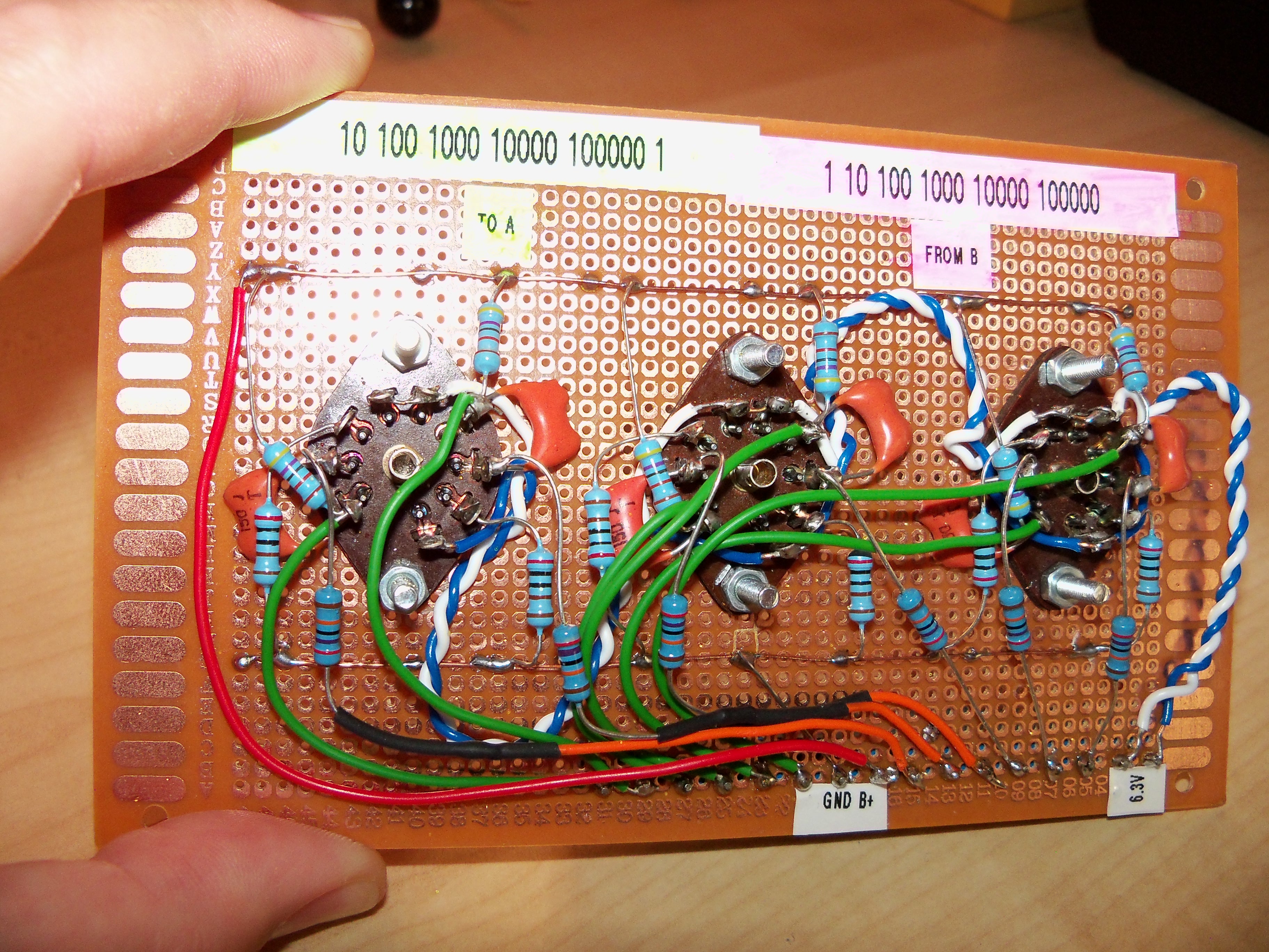
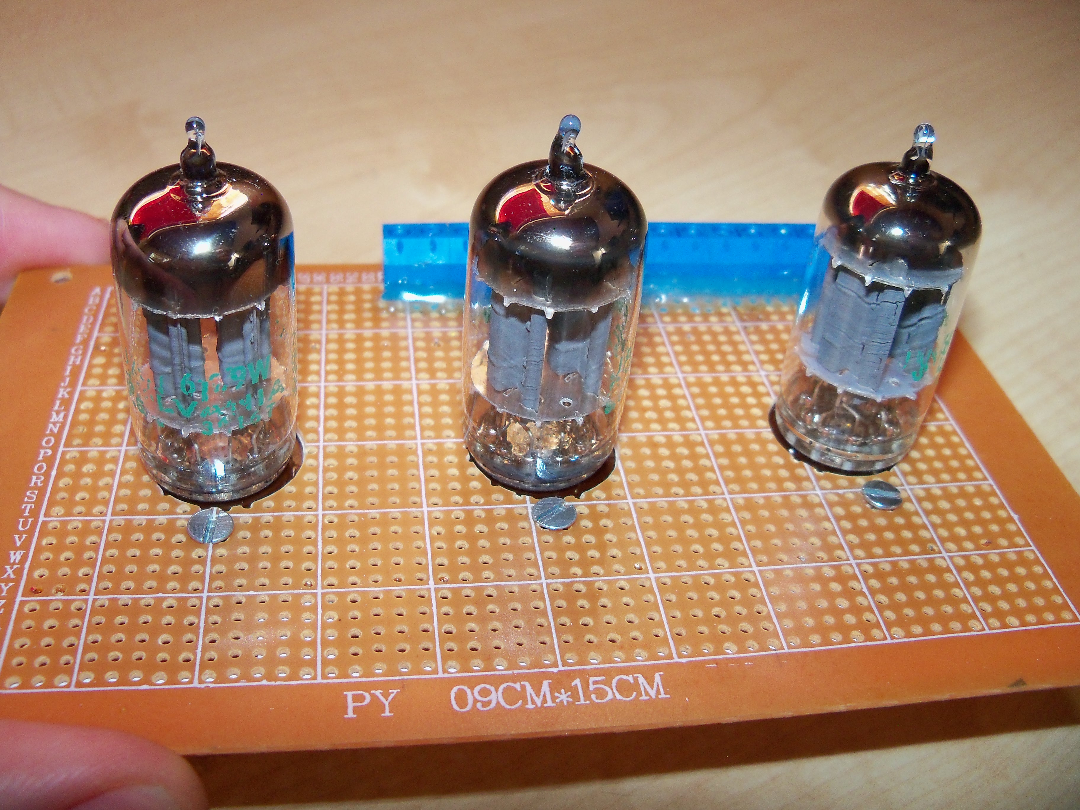
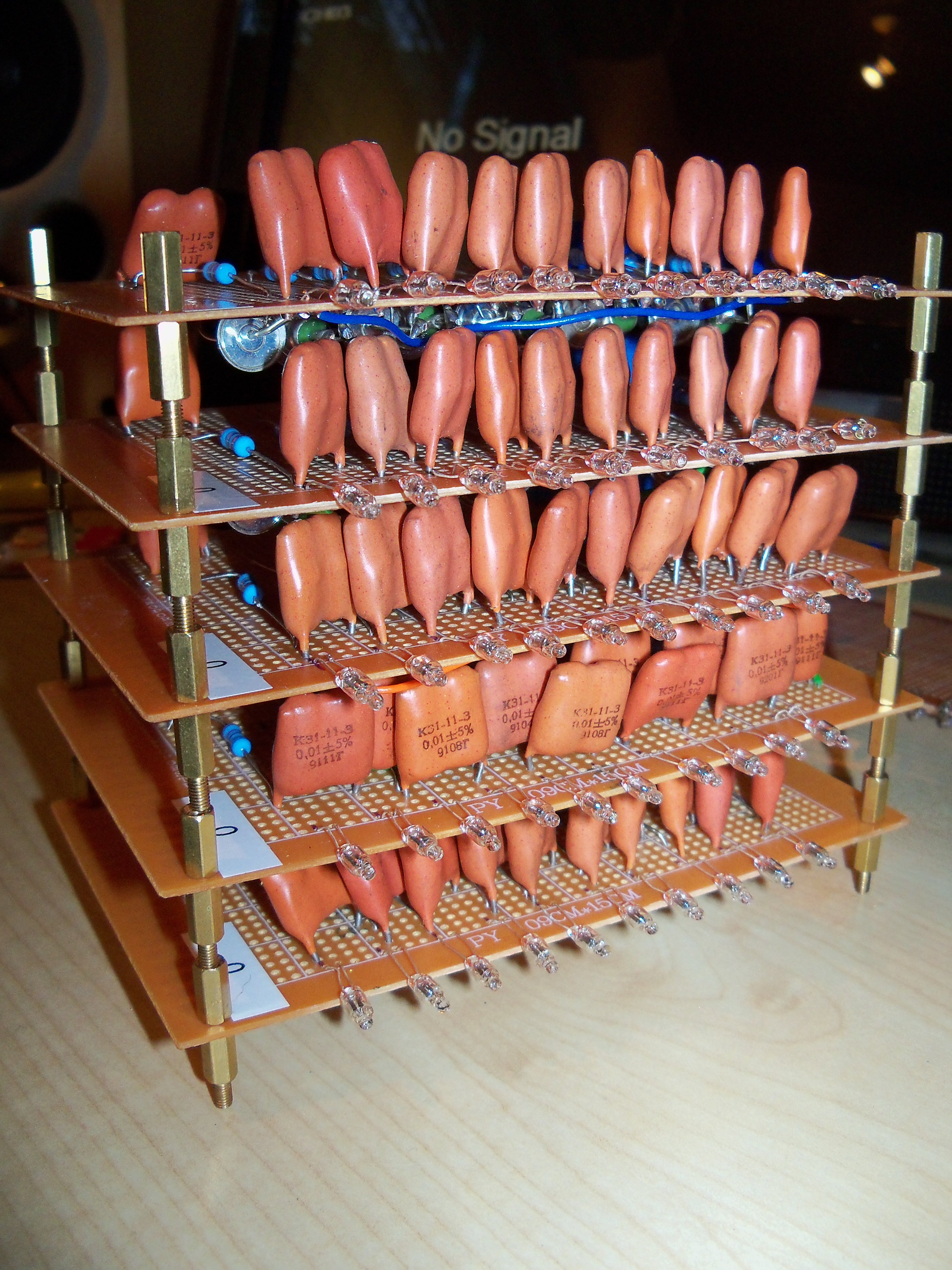
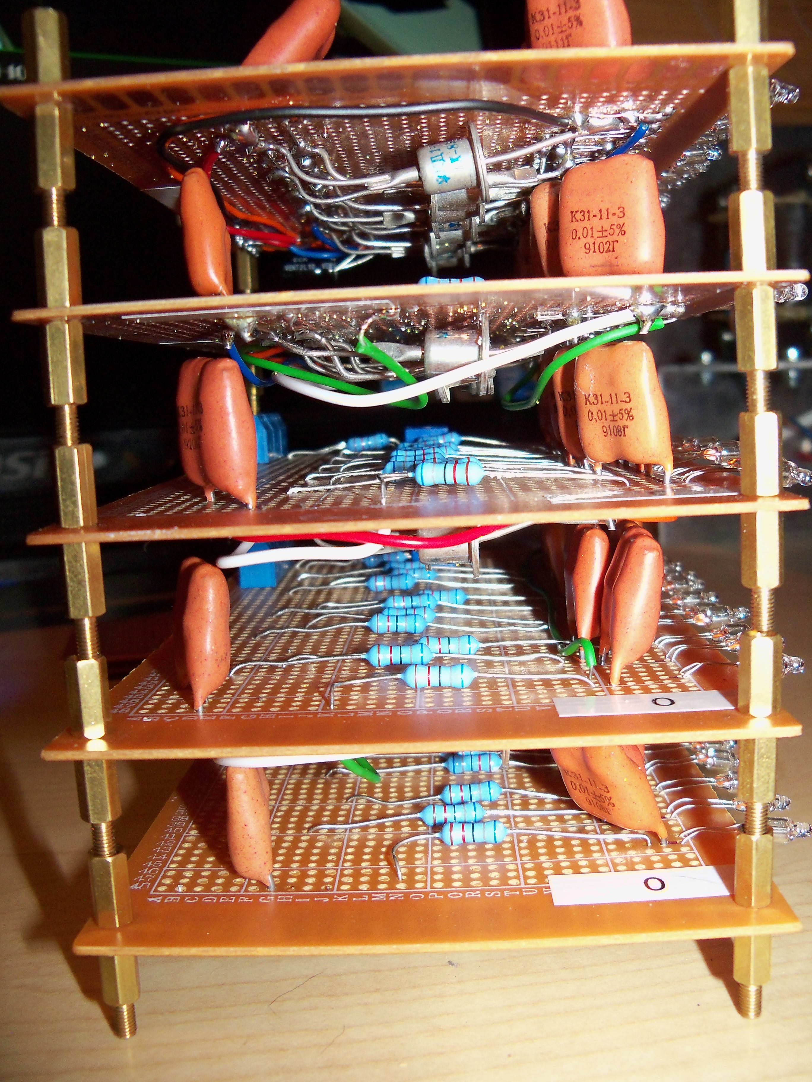
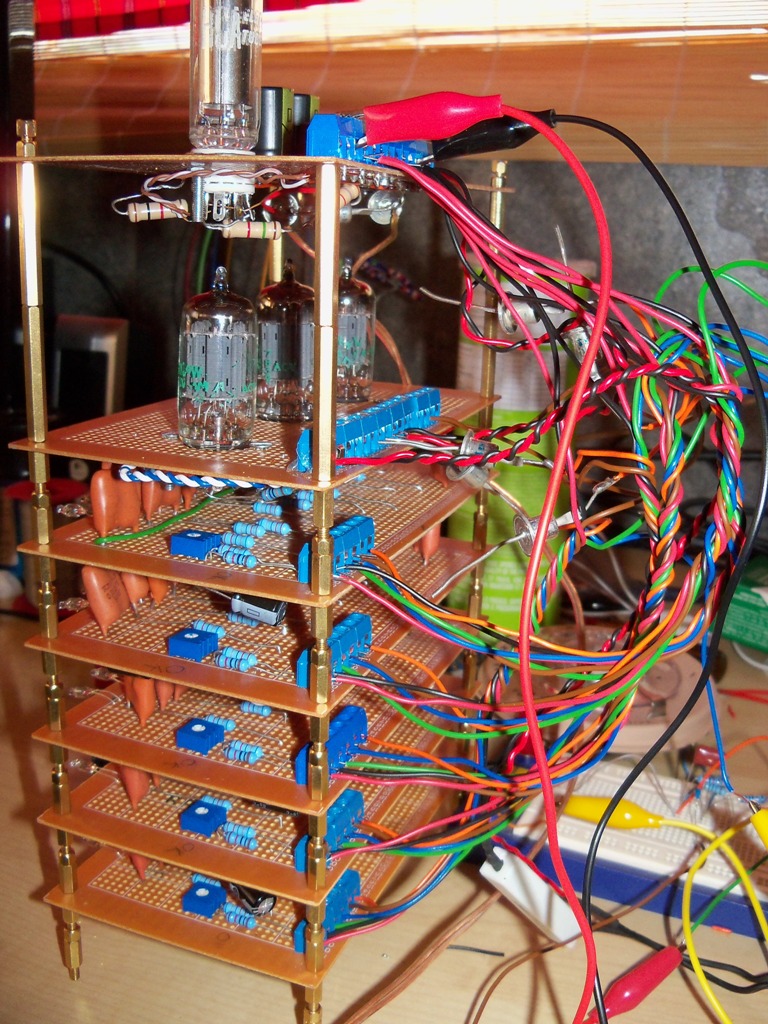
September 2014 I'm building an electronic calculator based on NE2 neon lamp ring counters. The design was originally published in Electronics Illustrated in November 1966. I find it frankly surprising that Electronics Illustrated used the circuit they did. In the "Transistor Manual," Seventh Edition, General Electric Co., 1964, p 203, a much more modern circuit is shown for a ring counter using transistors. Perhaps cost and component count was an issue. This was a very challenging design to get going reliably. I had to make some minor changes to the design. Even so, it is still not without some issues. Upon further reflection I think I will eventually rebuild this calculator using modern diodes and capacitors. Using vintage Russian diodes and capacitors might have looked cool, but the characteristics of these old components may no longer be good enough for this circuit. I'll re-use the power supply, and pulse amplifier boards. Only the ring counters need to be rebuilt.
1964 General Electric ring counter using transistors
Ring counter using neon lamps Below is a video of one of my neon ring counter boards being pulsed by a rotary telephone dial.
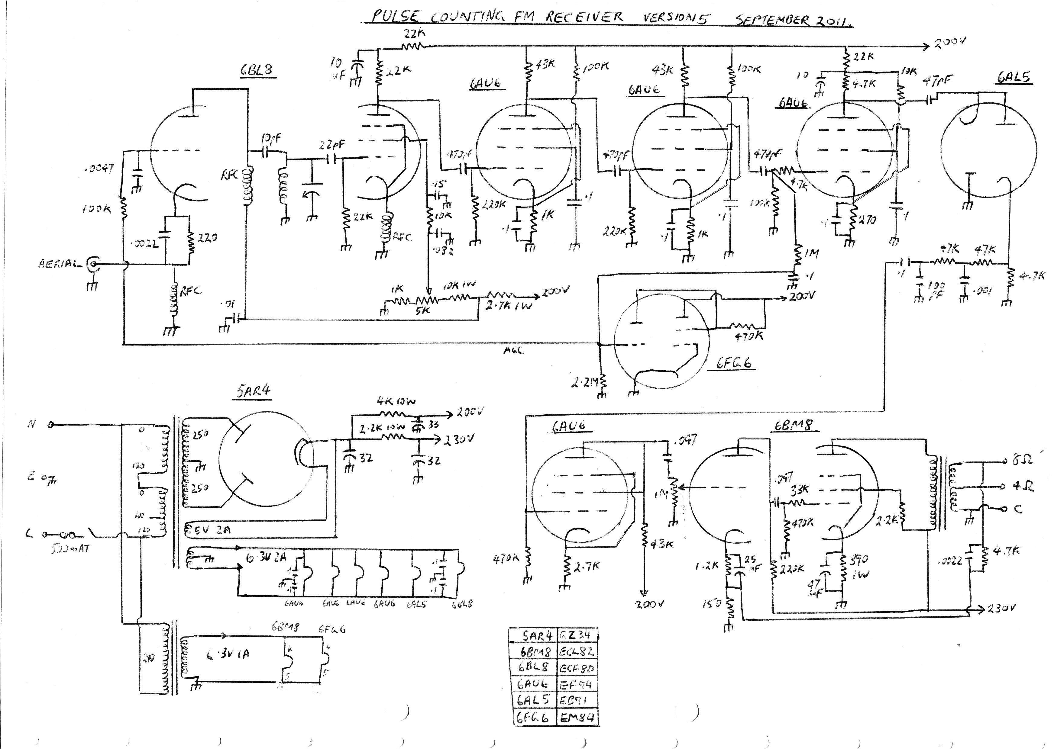
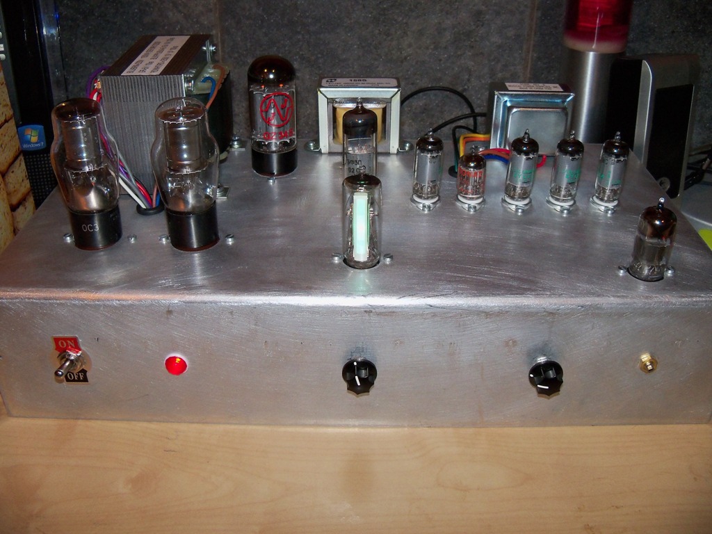
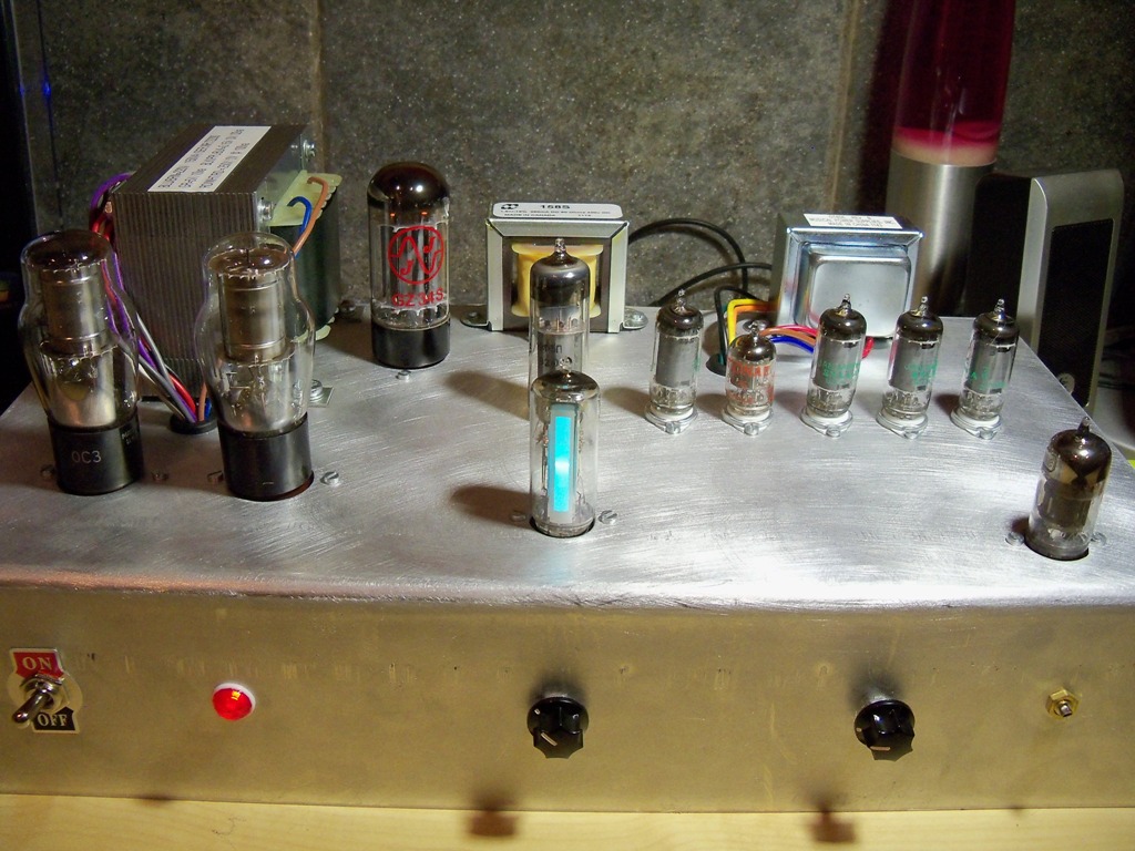
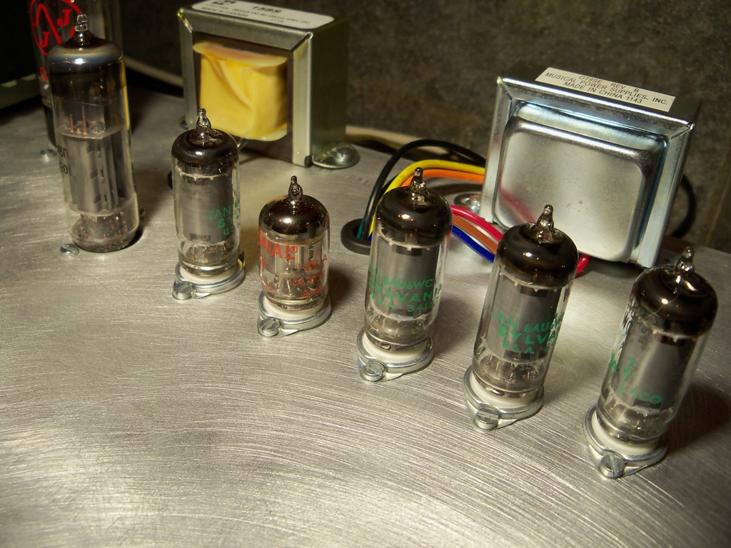
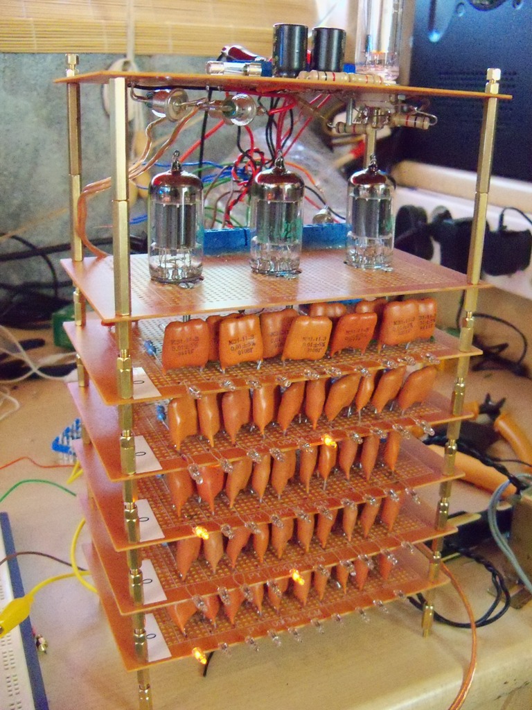
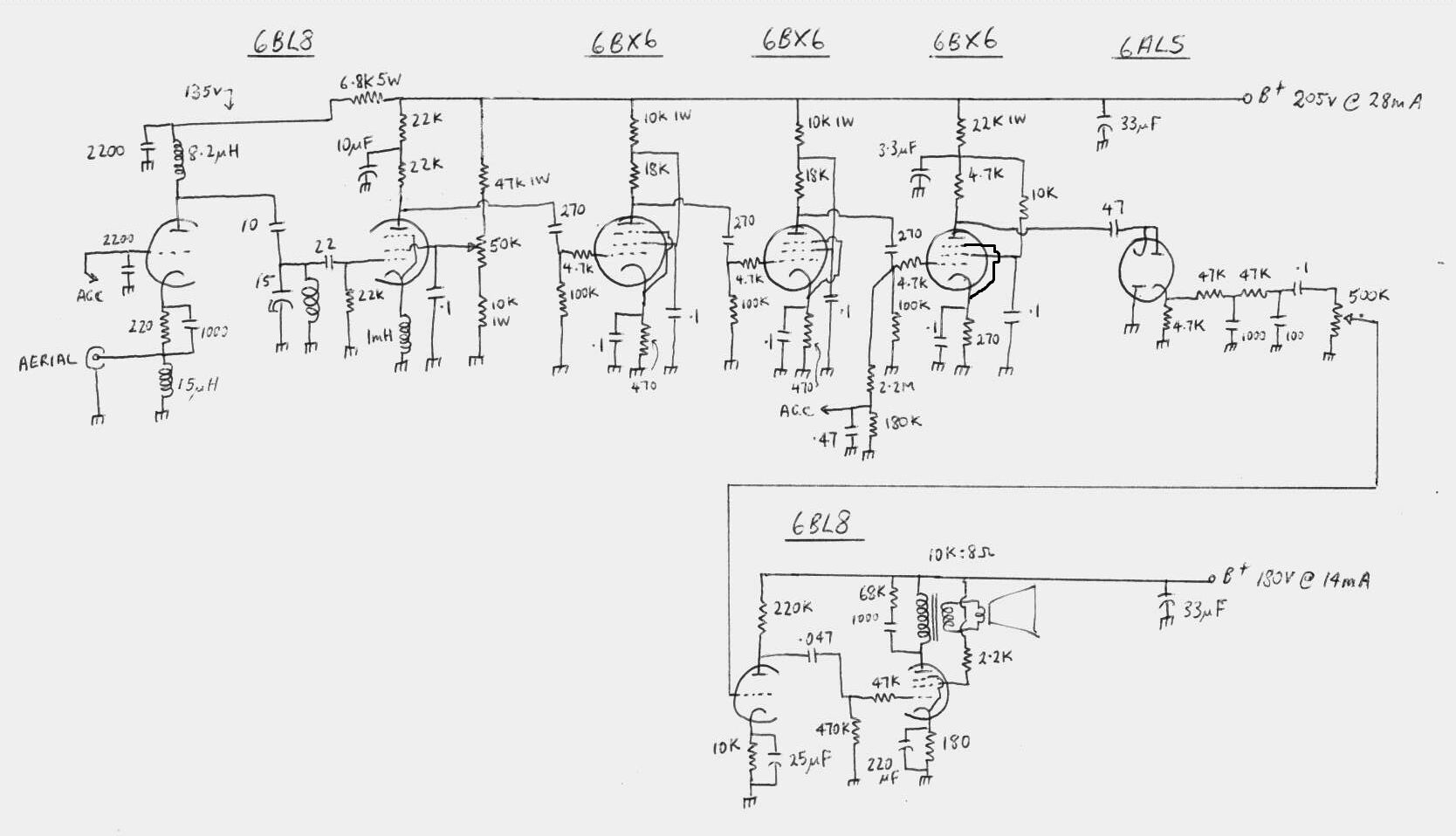
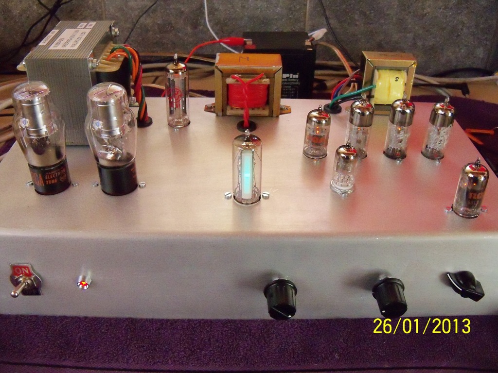
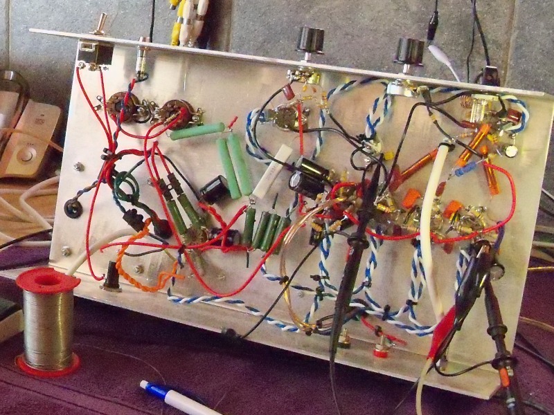
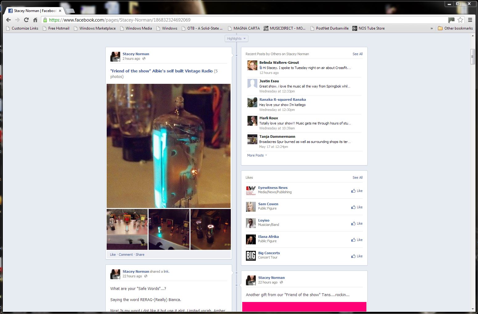
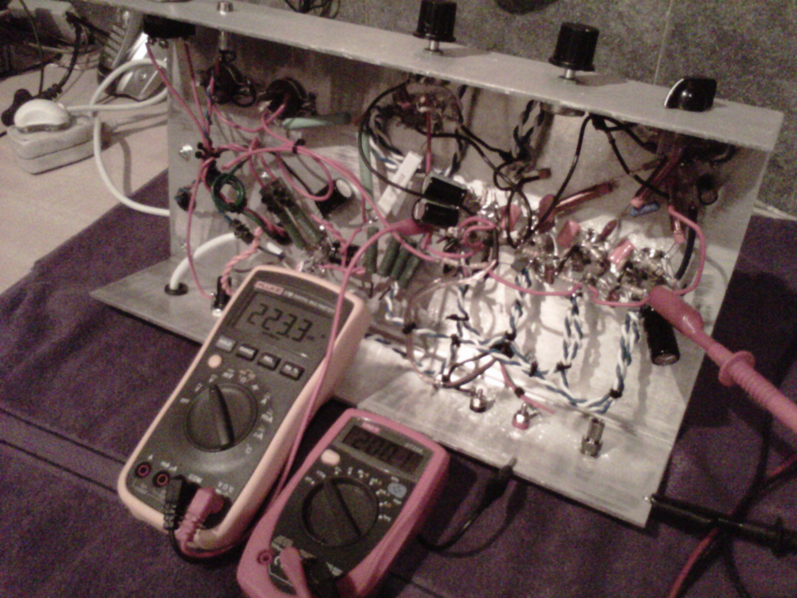
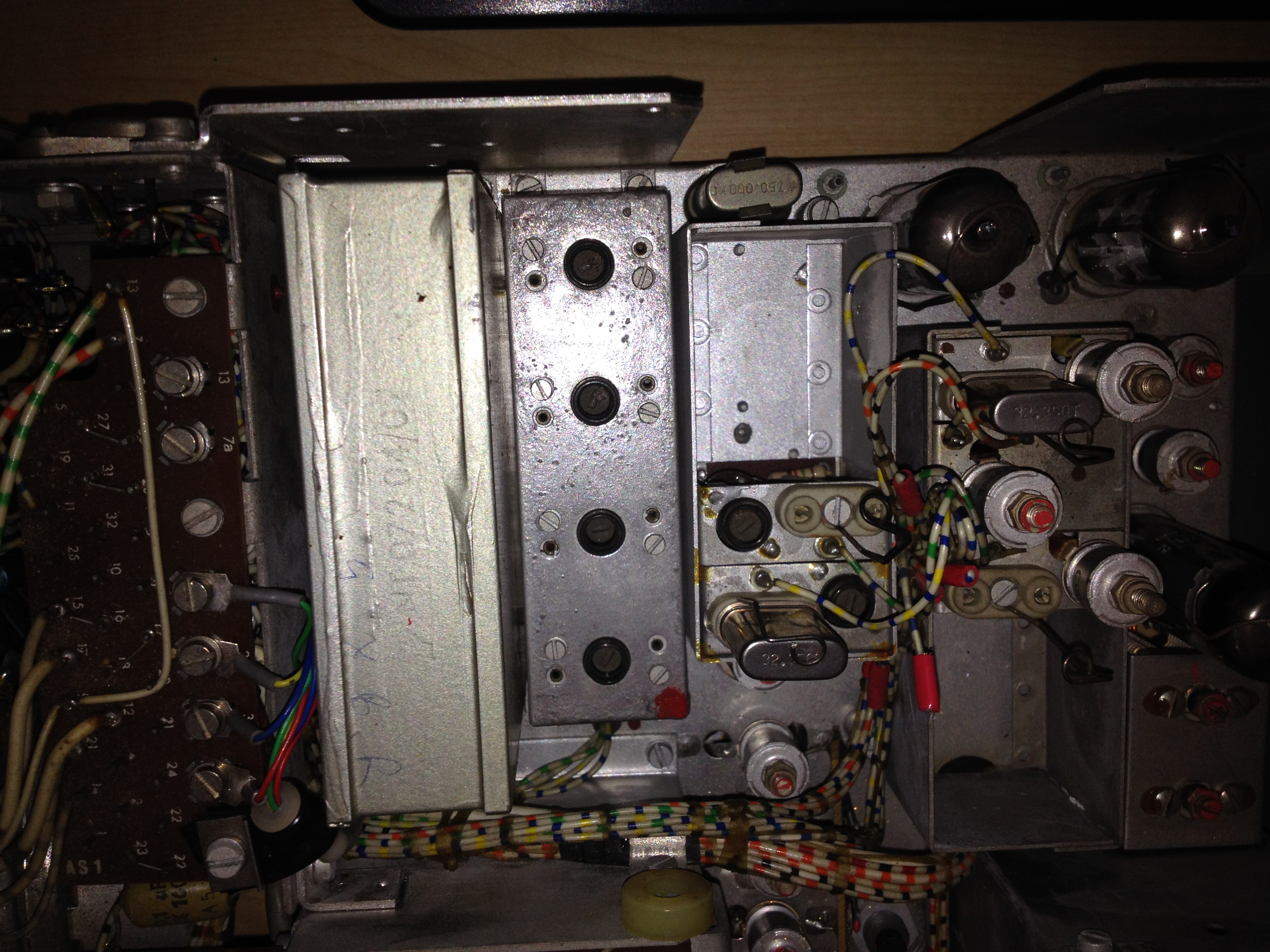
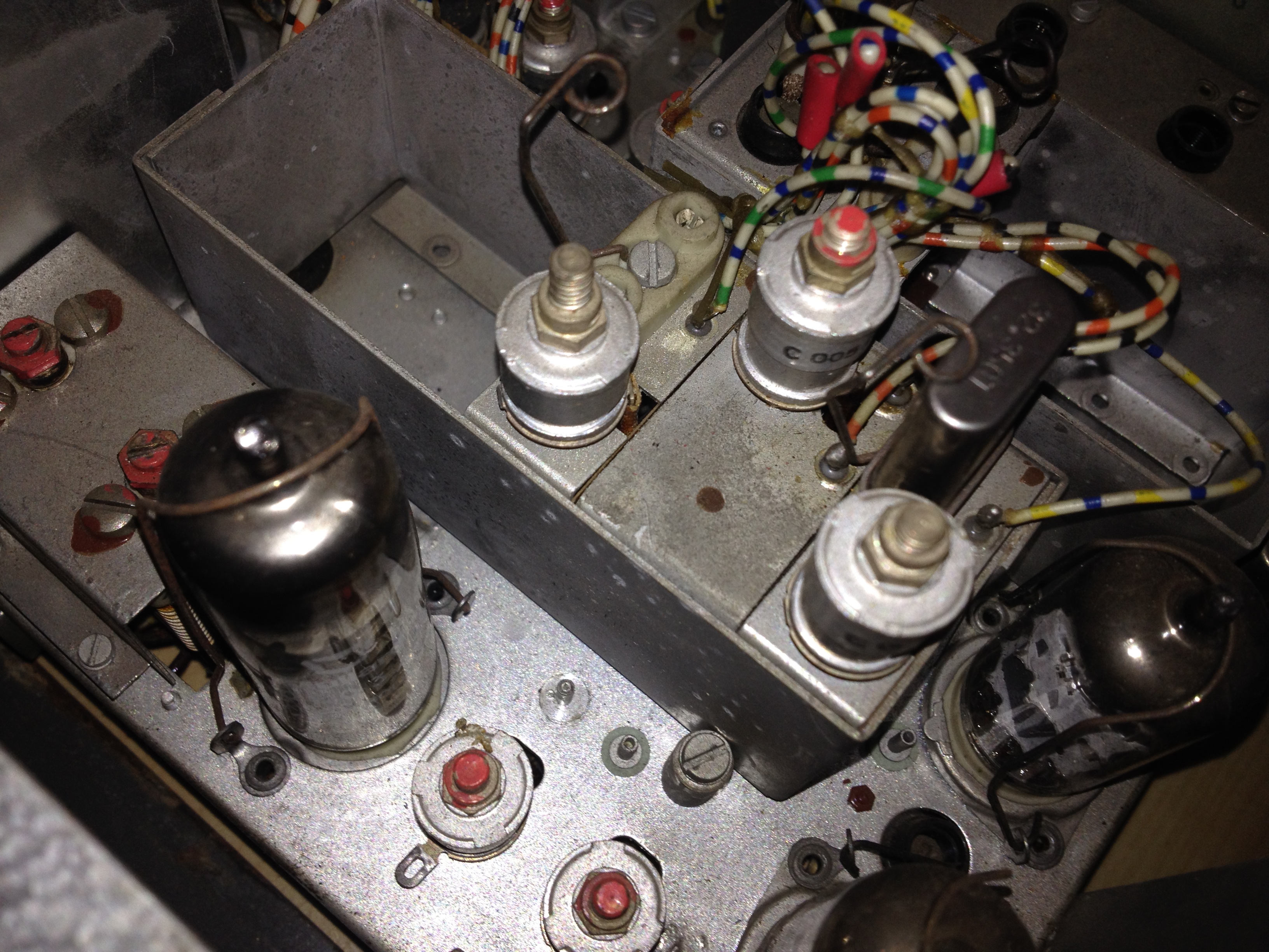
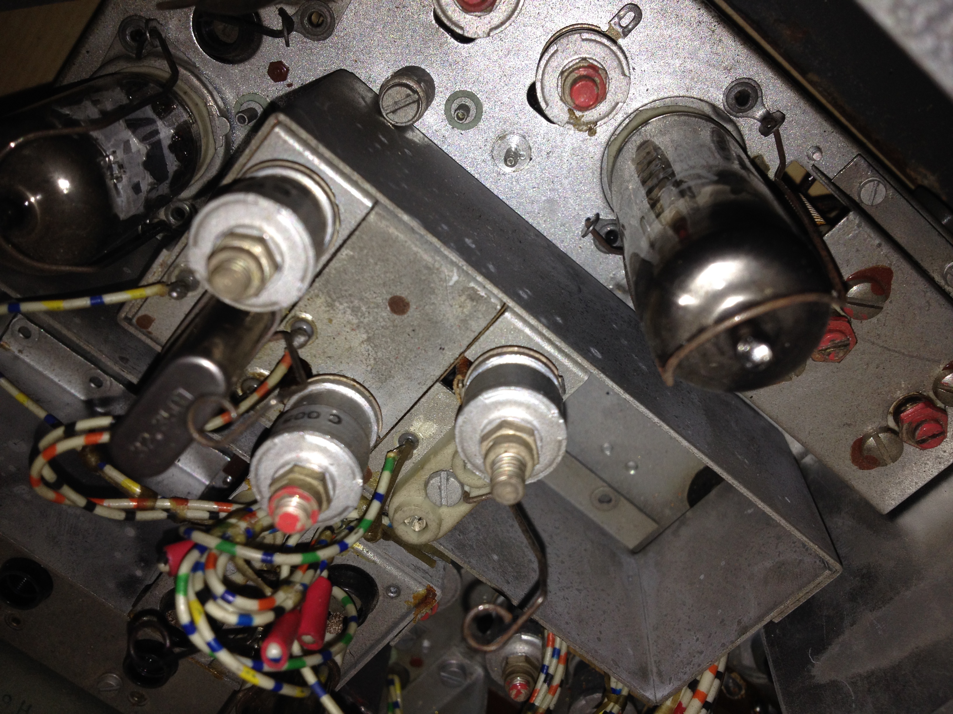
26 January 2013 This is an all vacuum tube Pulse Counting FM radio that I built. The chassis is 3mm aluminium that I had bent at a local engineering metal shop. I also sanded the metal to give it a matte finish. I drilled the socket mounting holes myself. The circuit uses heterodyning which means all incoming signals are mixed with a local oscillator. All signals are therefore down-converted to a much lower intermediate frequency (IF).
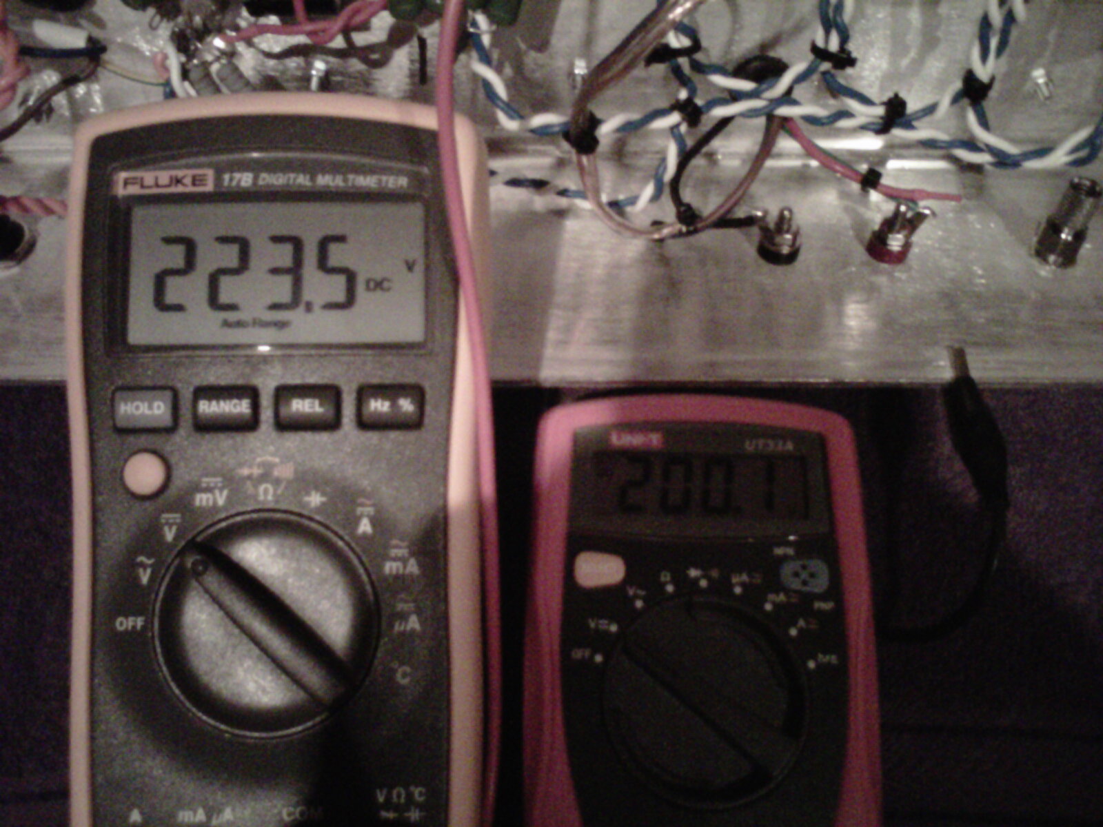
Schematic and original design by John This design is unique in that it uses an IF of only ~300kHz. There are no IF transformers and no need for alignment which makes for easy construction. Here's another implementation using a slightly different mixer/oscillator. I added OC3 gas voltage regulators to the design to help stabilise the power supply. The local oscillator benefits from a stable supply voltage. The tube heaters are AC powered and there is no detectable hum. Proper tube heater wiring guidelines were followed like twisting the wires together tightly, not making wiring loops and keeping the wiring away from the sockets. A small bypass capacitor is wired across each heater and the heater wiring is grounded at the VHF local oscillator only. The set uses EF80 x 3, 6AL5 x 1, 6BL8 x 2, EZ81 x 1, OC3 x 2 and an EM84 magic eye. B+ is ~200V. The main power transformer is from Eloff Transformers. The power supply filter choke is a rewound transformer core. The audio output transformer was "borrowed" from an unused tube audio amp kit I bought that had poor performance. All tubes are NOS. The EZ81 is running with 200ohm protection resistors. I had to make some other very minor adjustments to maximise the sensitivity. It now pulls in stations loud and clear from Tygerberg hill 30km away using a rooftop Yagi. Sound quality is Hi-Fi.
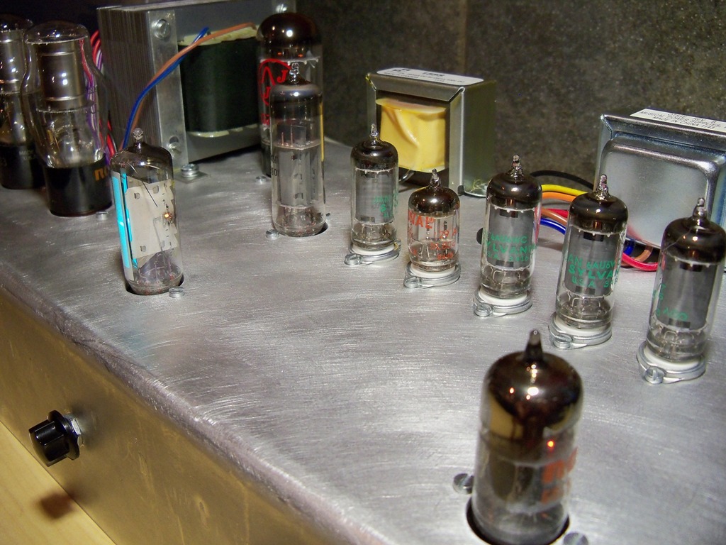
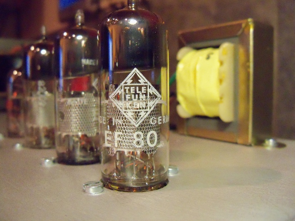
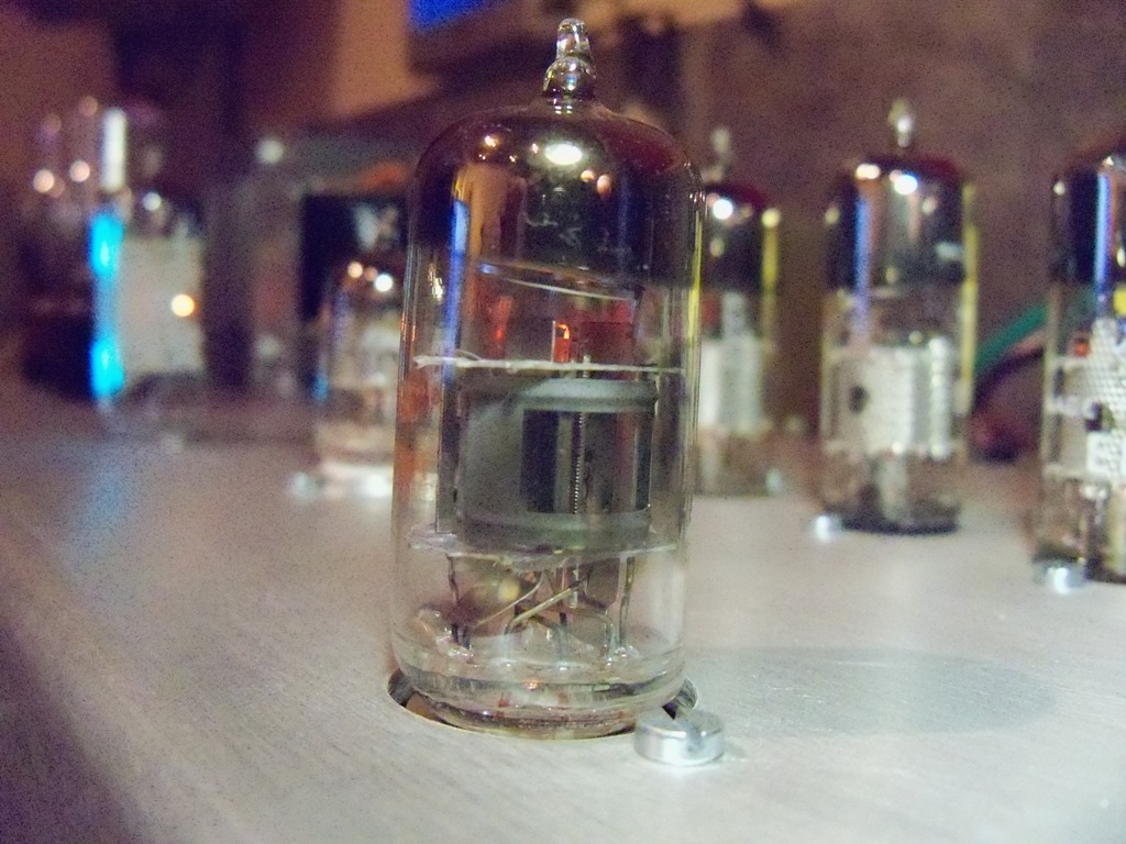
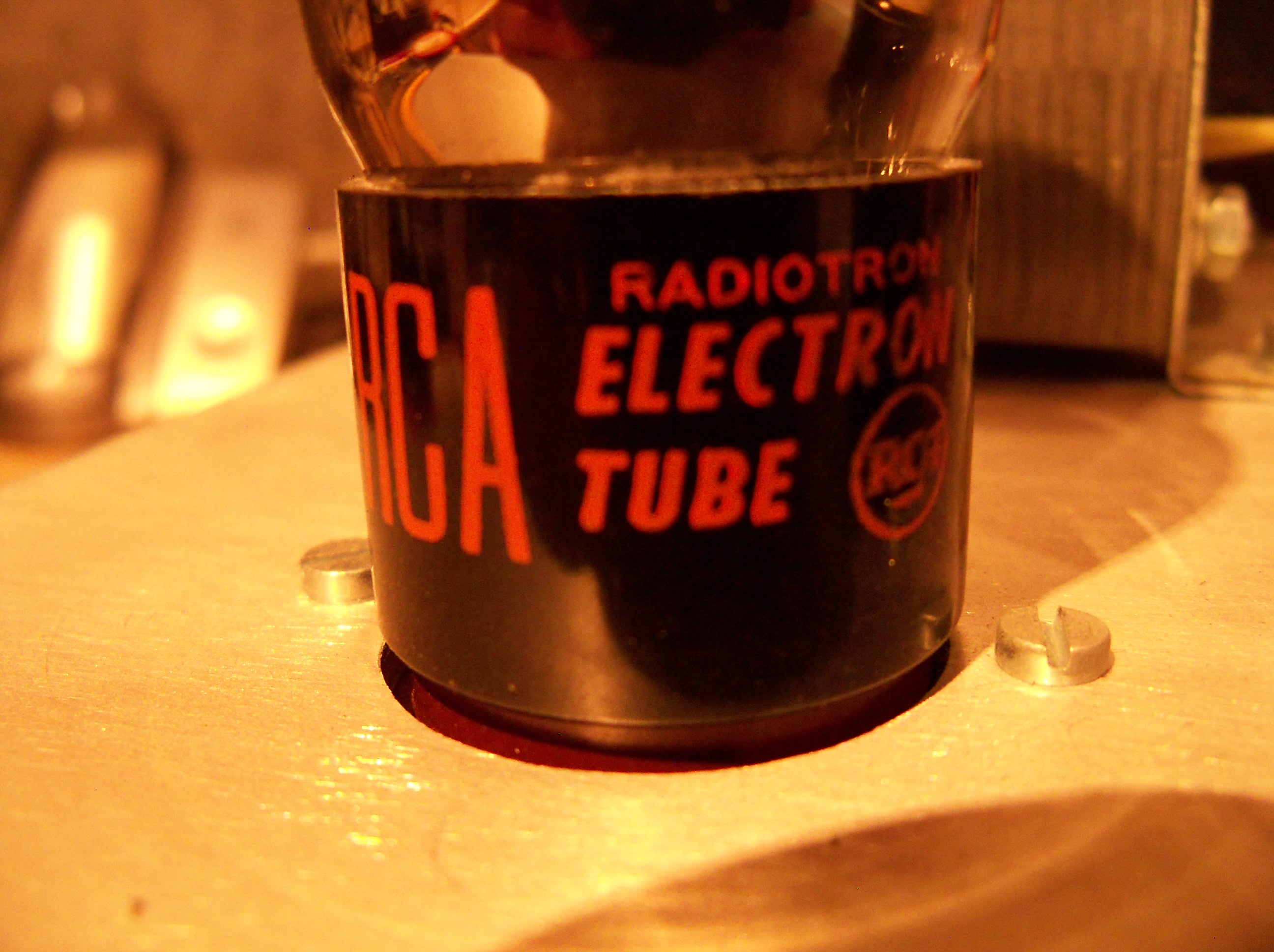
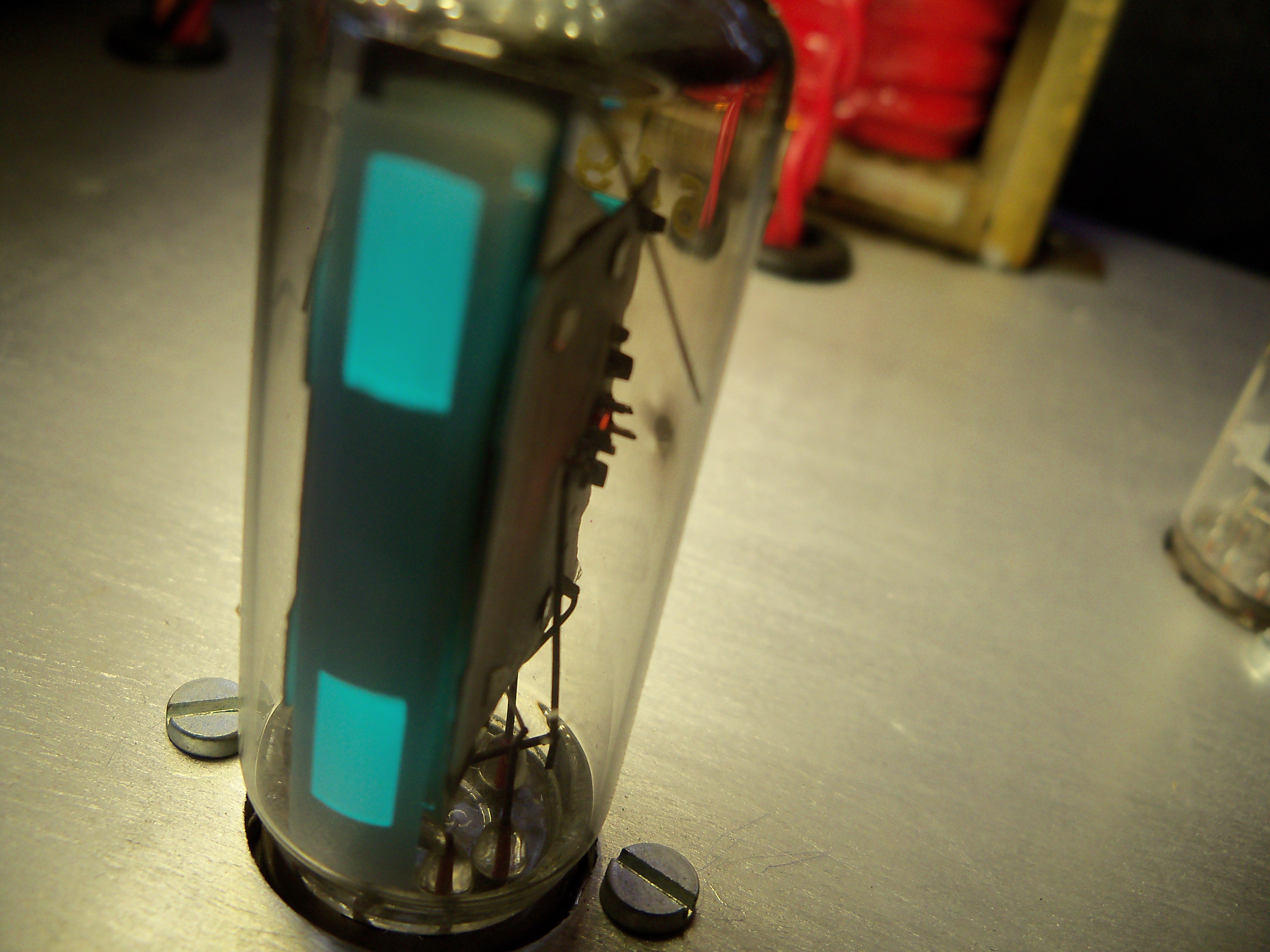
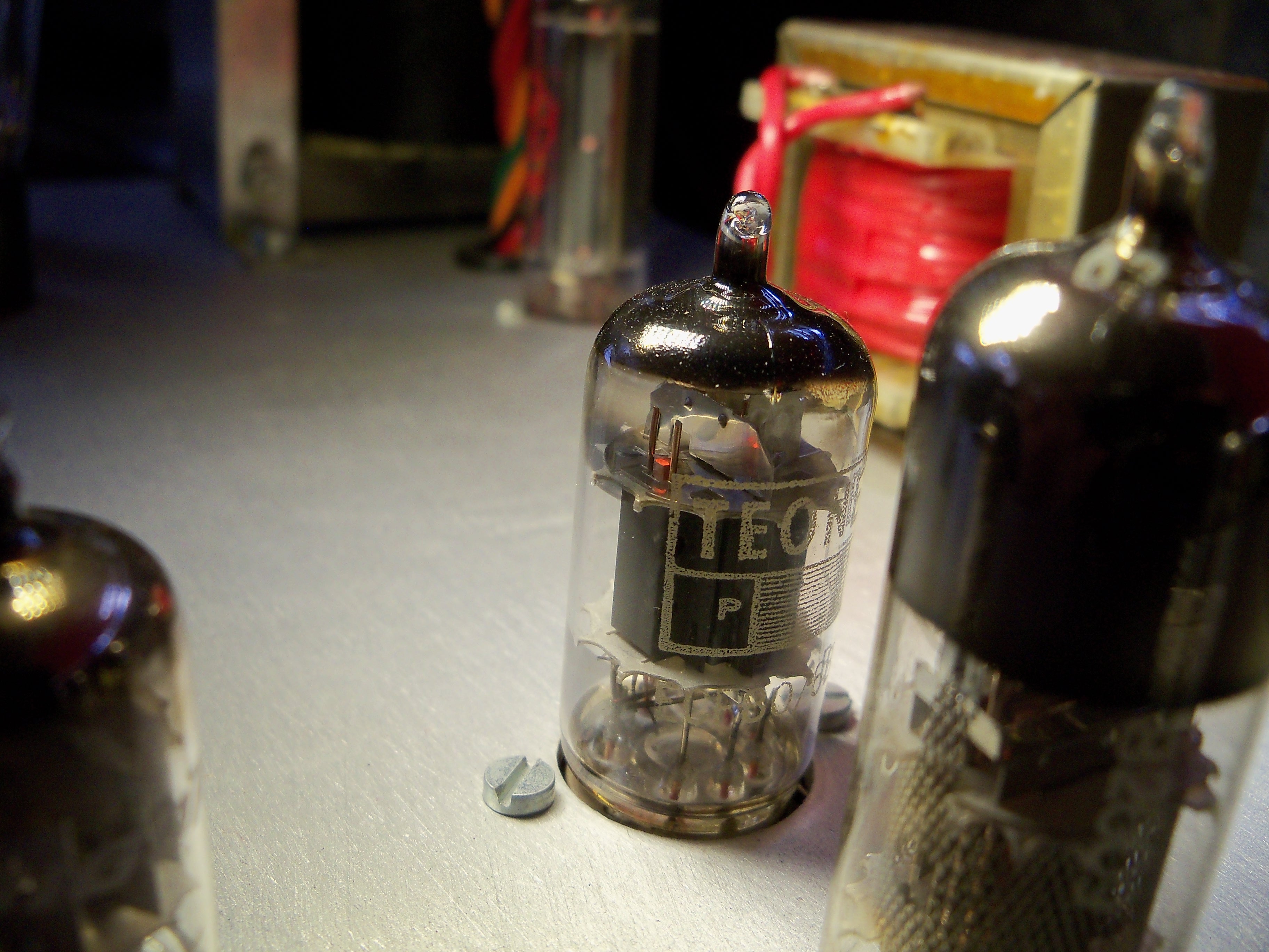
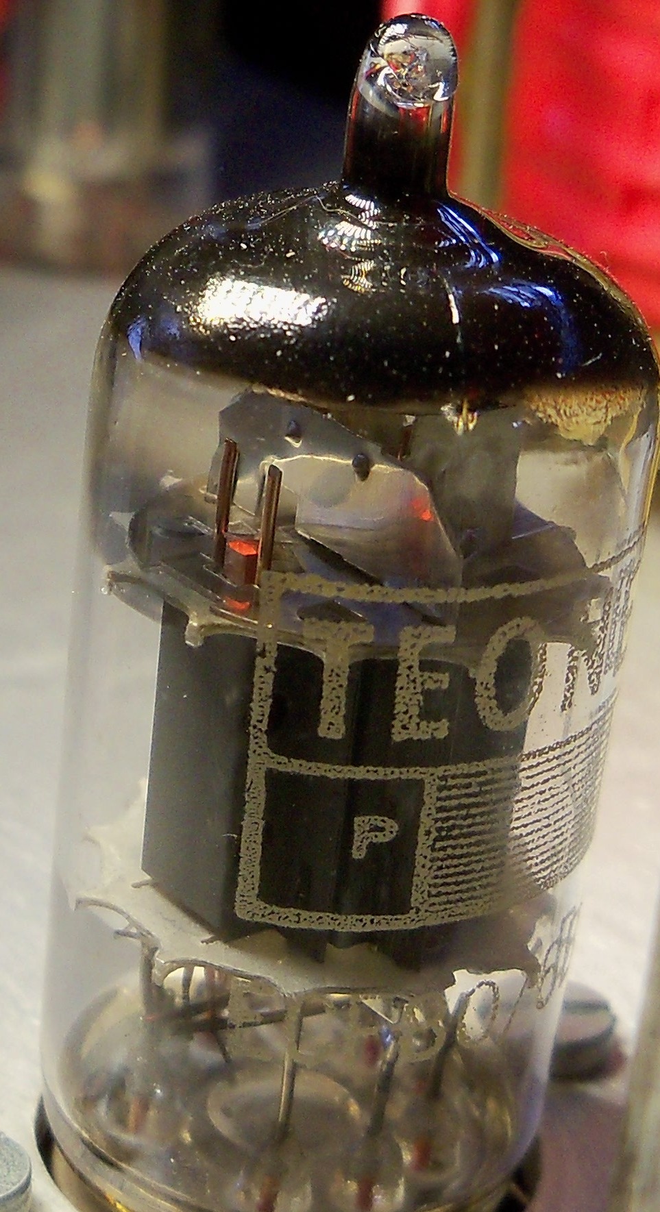
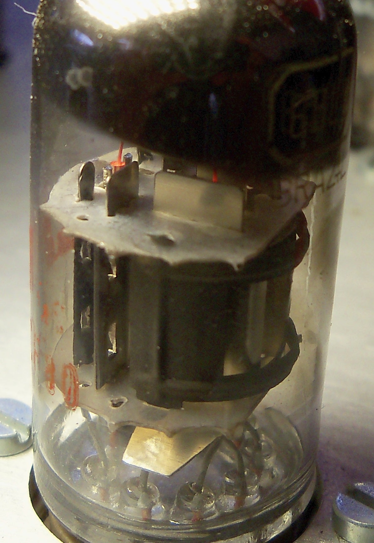
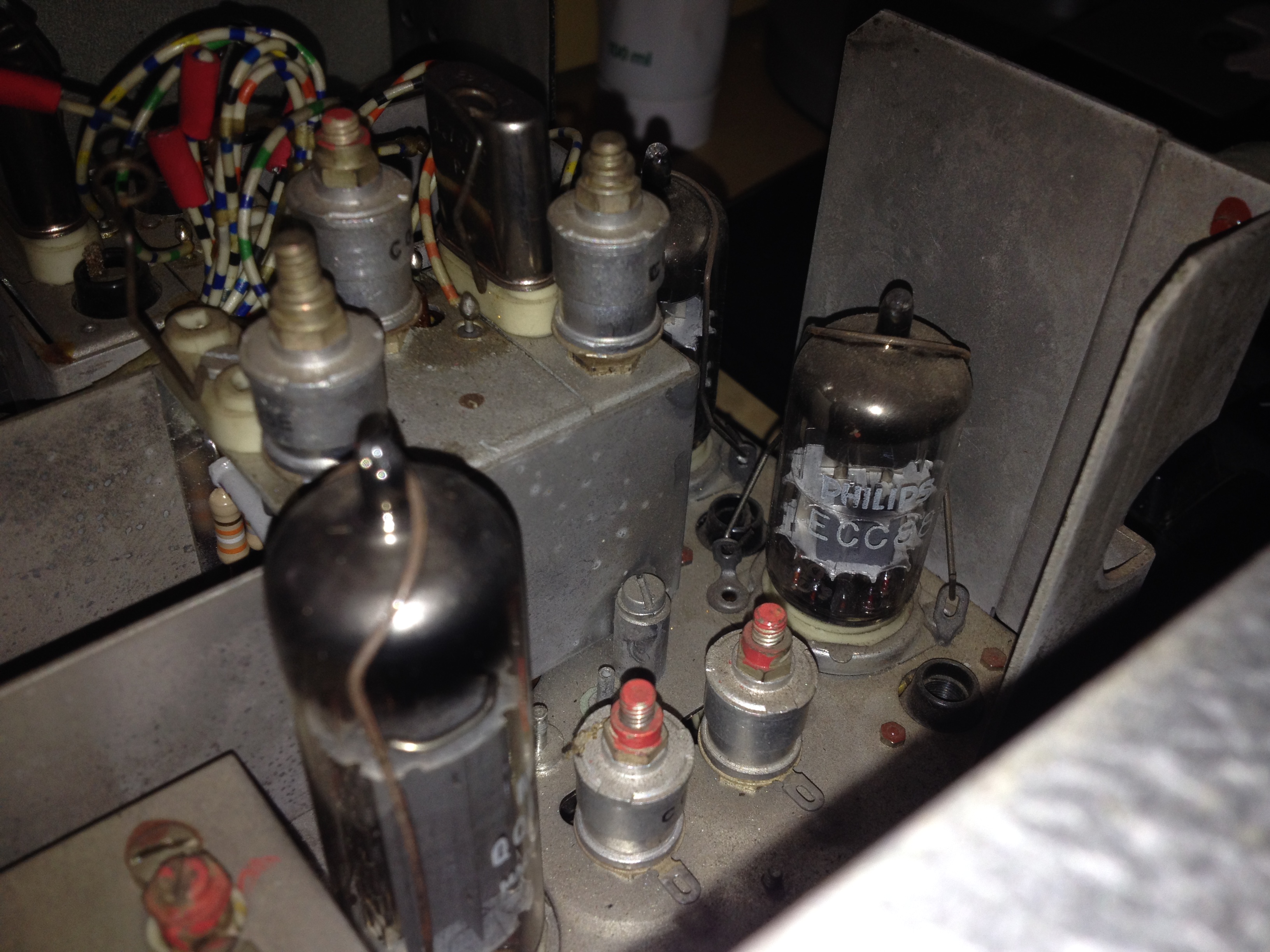
20 June 2013 I recently bought some "Made in England" Teonex 6BL8/ECF80 tubes and tried one out in the VHF tuner section of my Pulse Counter FM radio. The radio worked, but would only tune to relatively strong stations. Weaker stations could not be tuned in at all. It was obvious that the sensitivity was a lot less. I put the RCA 6BL8 that I took out back and all was well again. Even the weaker stations came in loud and clear. I took a closer look at the RCA and Teonex tube and noticed that the anode structure of the pentode section was completely different between the two tubes. The RCA 6BL8 has a half-moon shaped anode with a large rectangular cut-out through which the cathode and pentode grids are visible. The Teonex on the other hand has a closed box type anode. Teonex relabelled tubes from European, but also Japanese manufacturers. See photos below. It turns out the 6BL8 was never intended to be used in this configuration where the pentode section acts as both mixer and oscillator. The triode was supposed to be the oscillator, but in Johns' design the triode section acts as a buffer amplifier between the aerial and the pentode oscillator/mixer. It is conceivable that manufacturers therefore never tested their 6BL8/ECF80 in this configuration and differences in design had a marked effect when the pentode was used as mixer and oscillator.
I e-mailed John In Australia with my information. Here's his response:
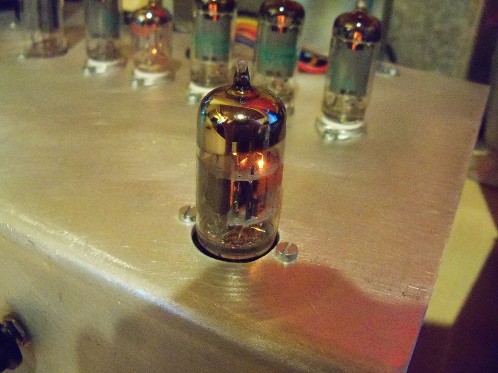
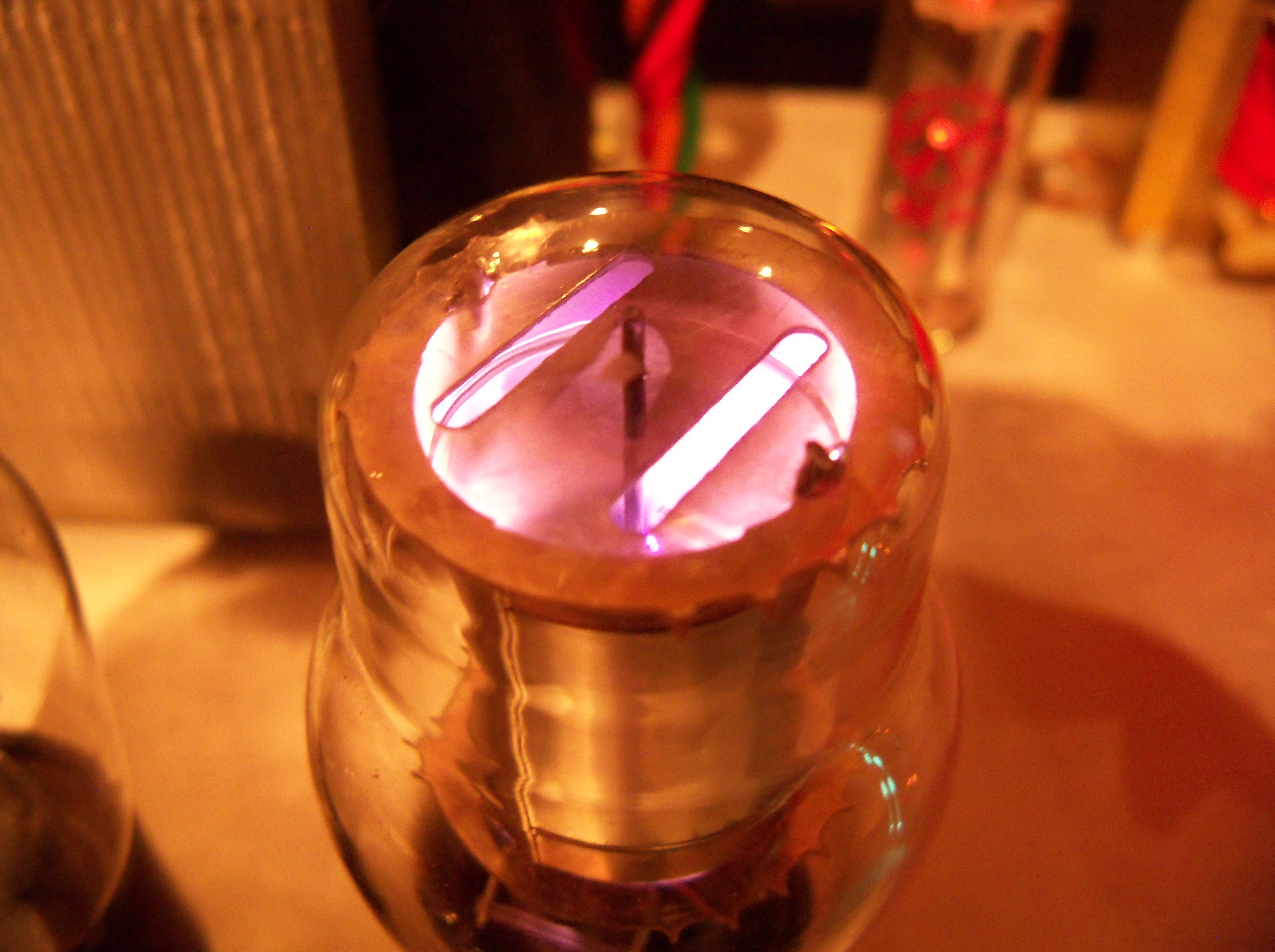
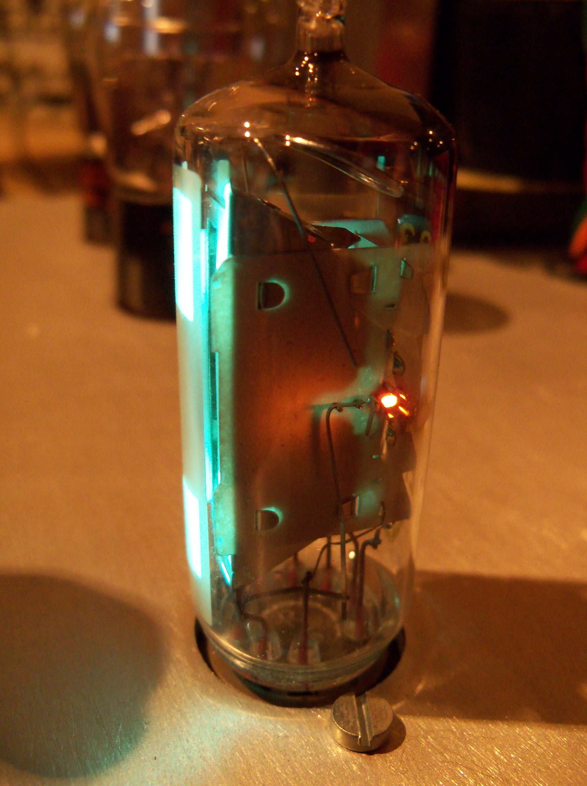
9 February 2014 I noticed that all of the tubes in my radio have developed some discoloration on the inside of the glass. It varies in darkness and severity. These tubes now have in excess of 3000 hours on them. I'm at a loss to completely explain the discoloration. My Internet research reveals that electron bombardment does indeed discolour glass. Ion bombardment is also a possibility. The discoloration does not appear to affect the operation of the tubes and my radio works perfectly. I think the most likely culprit is prolonged electron bombardment.
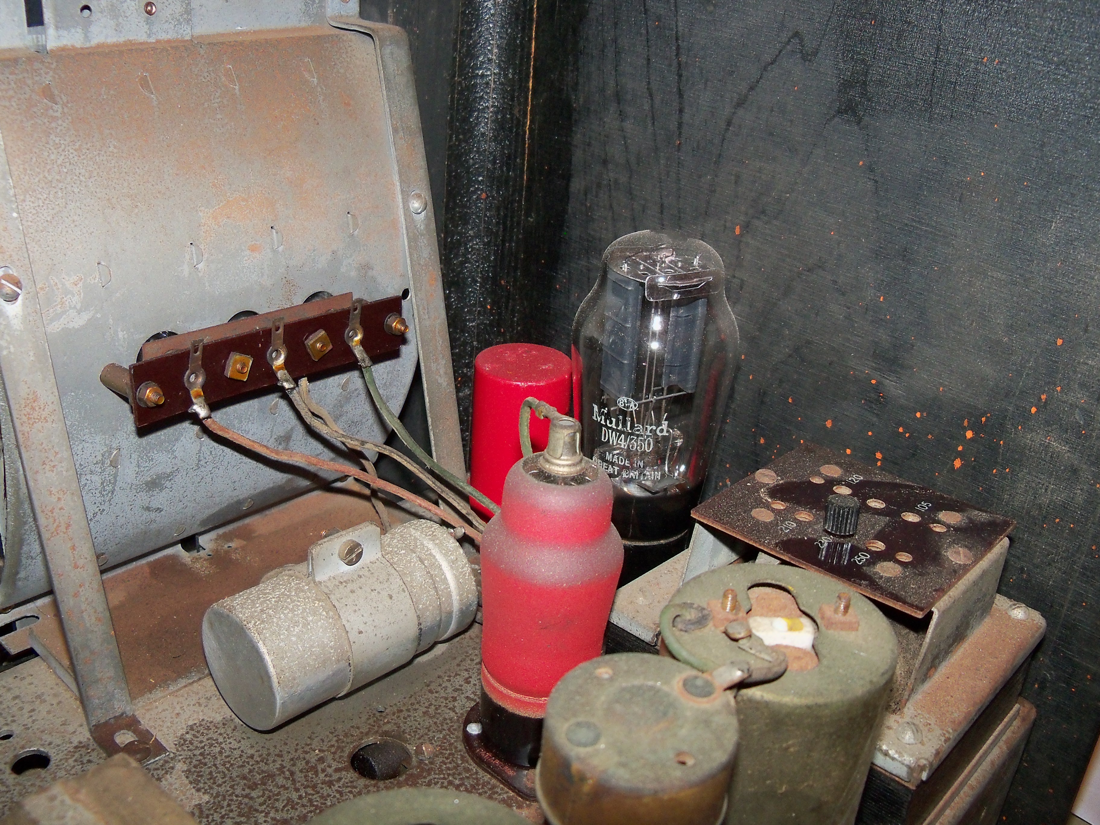
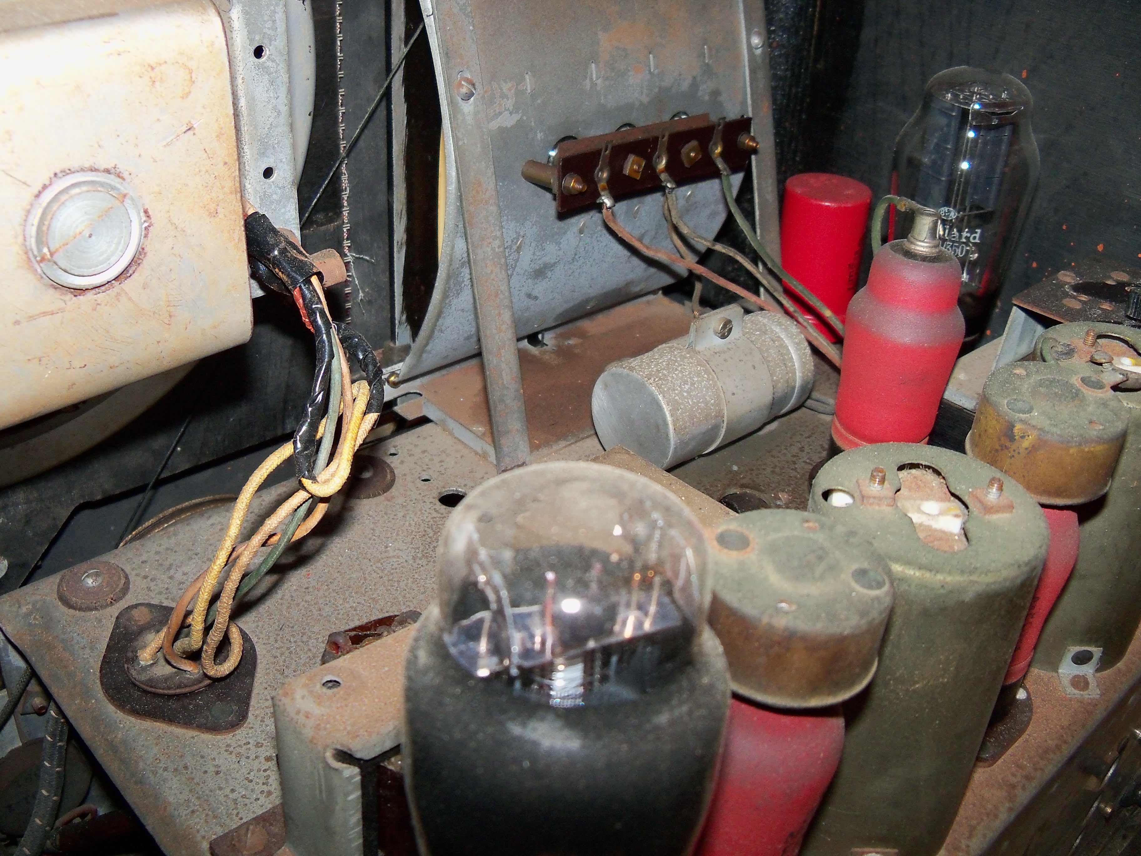
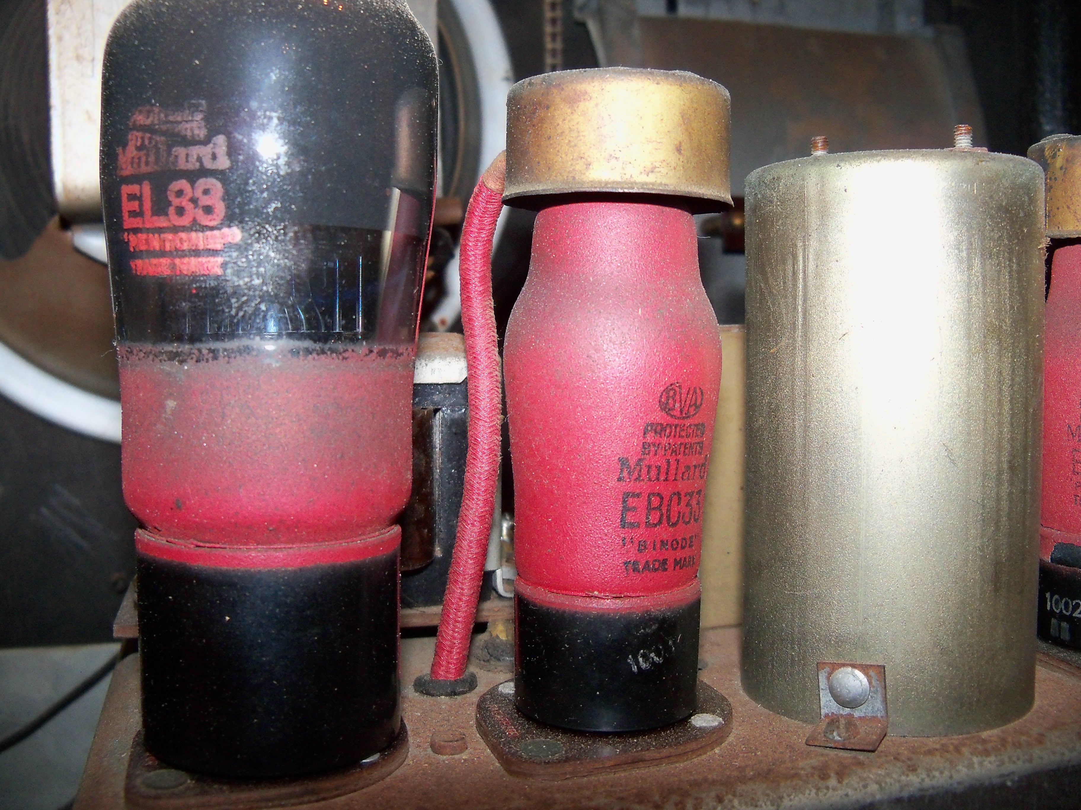
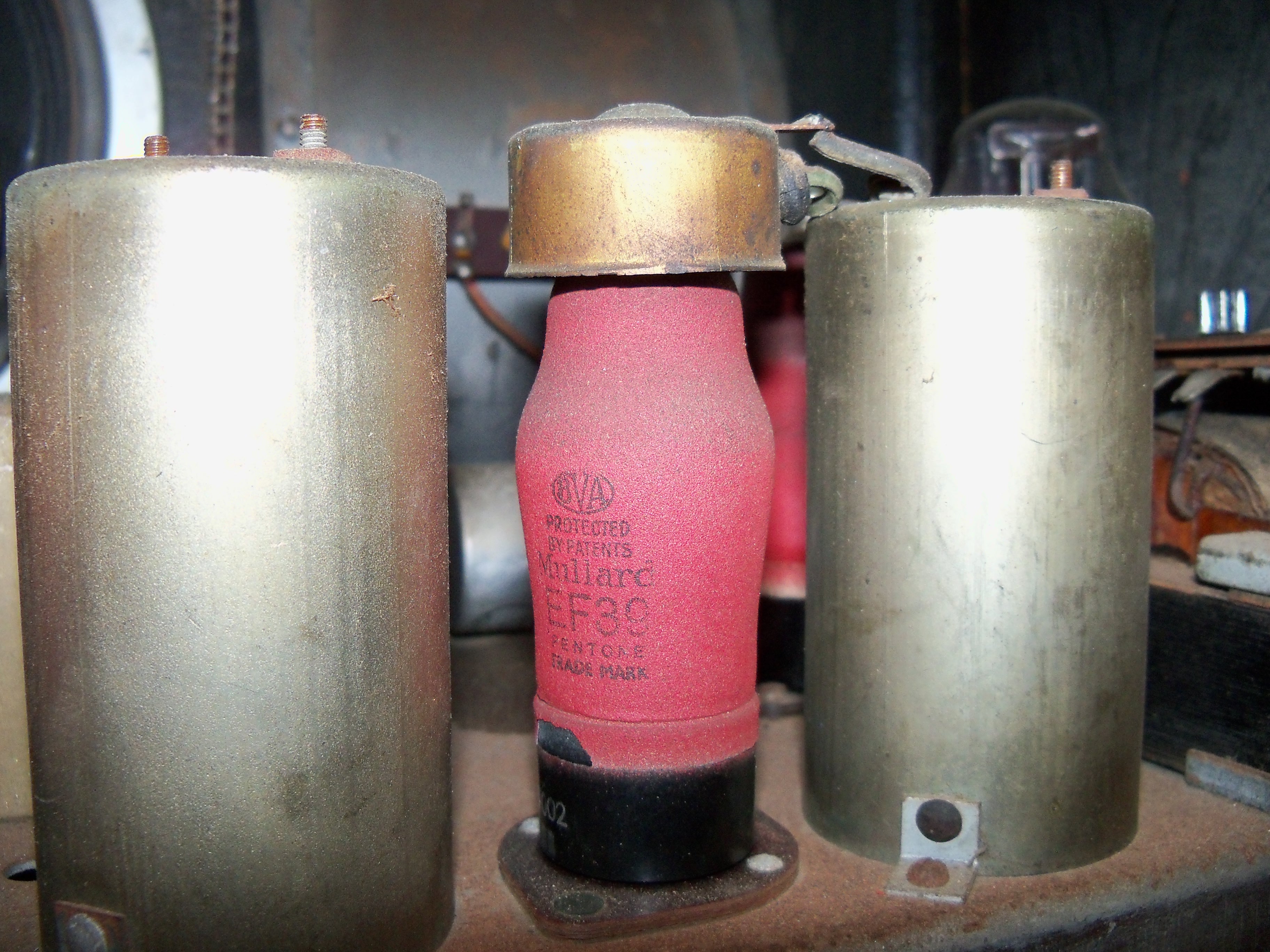
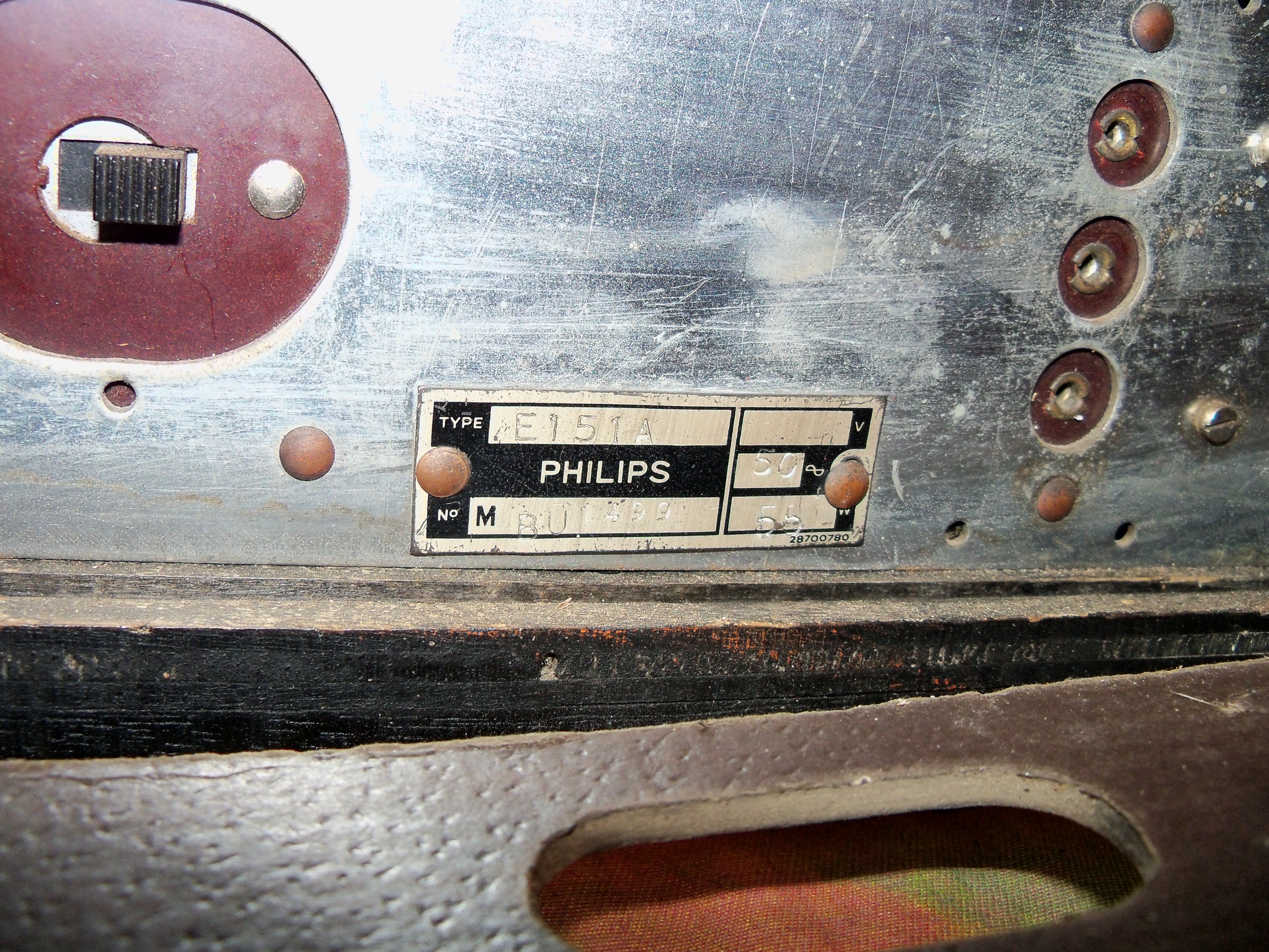
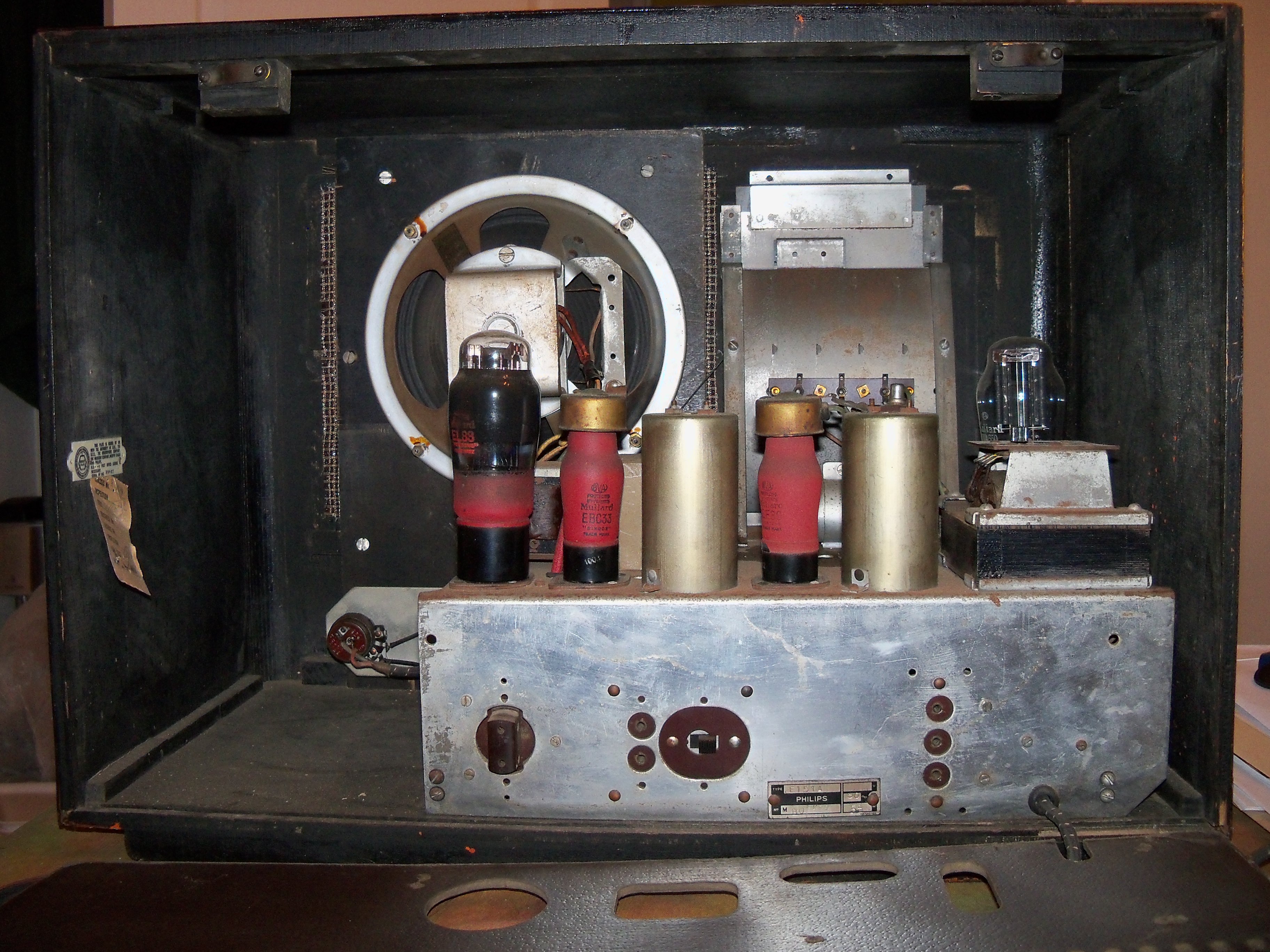
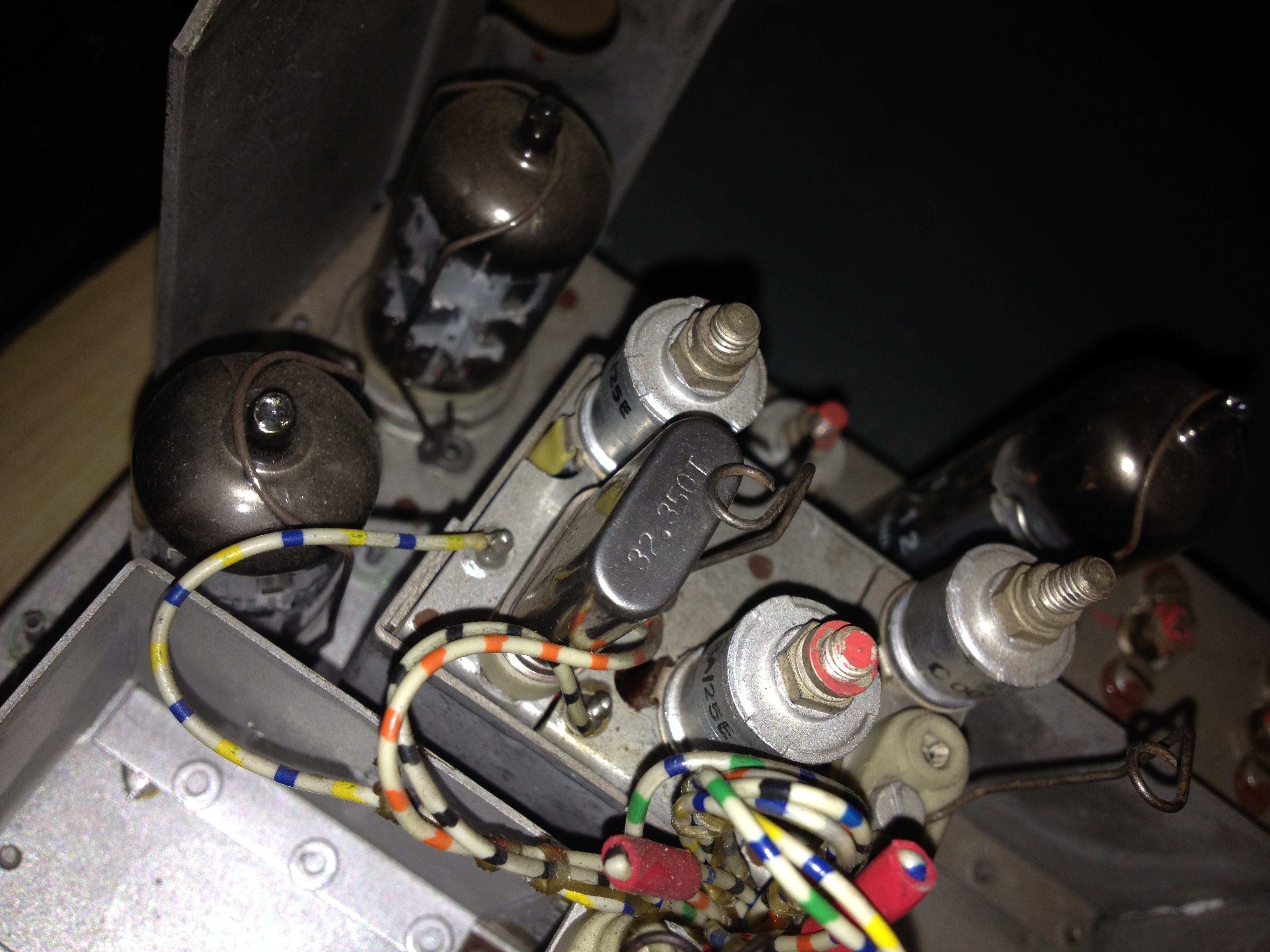
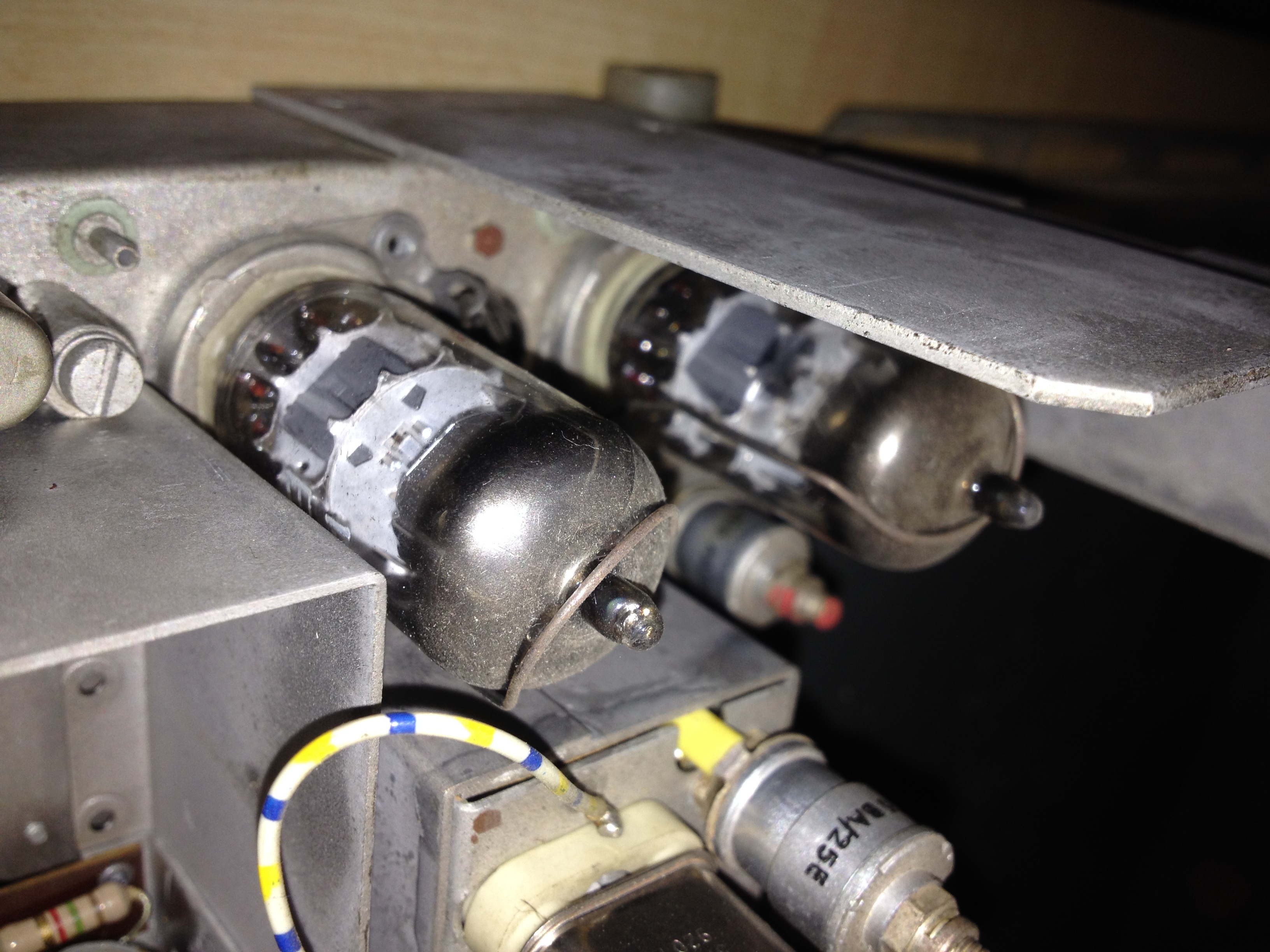
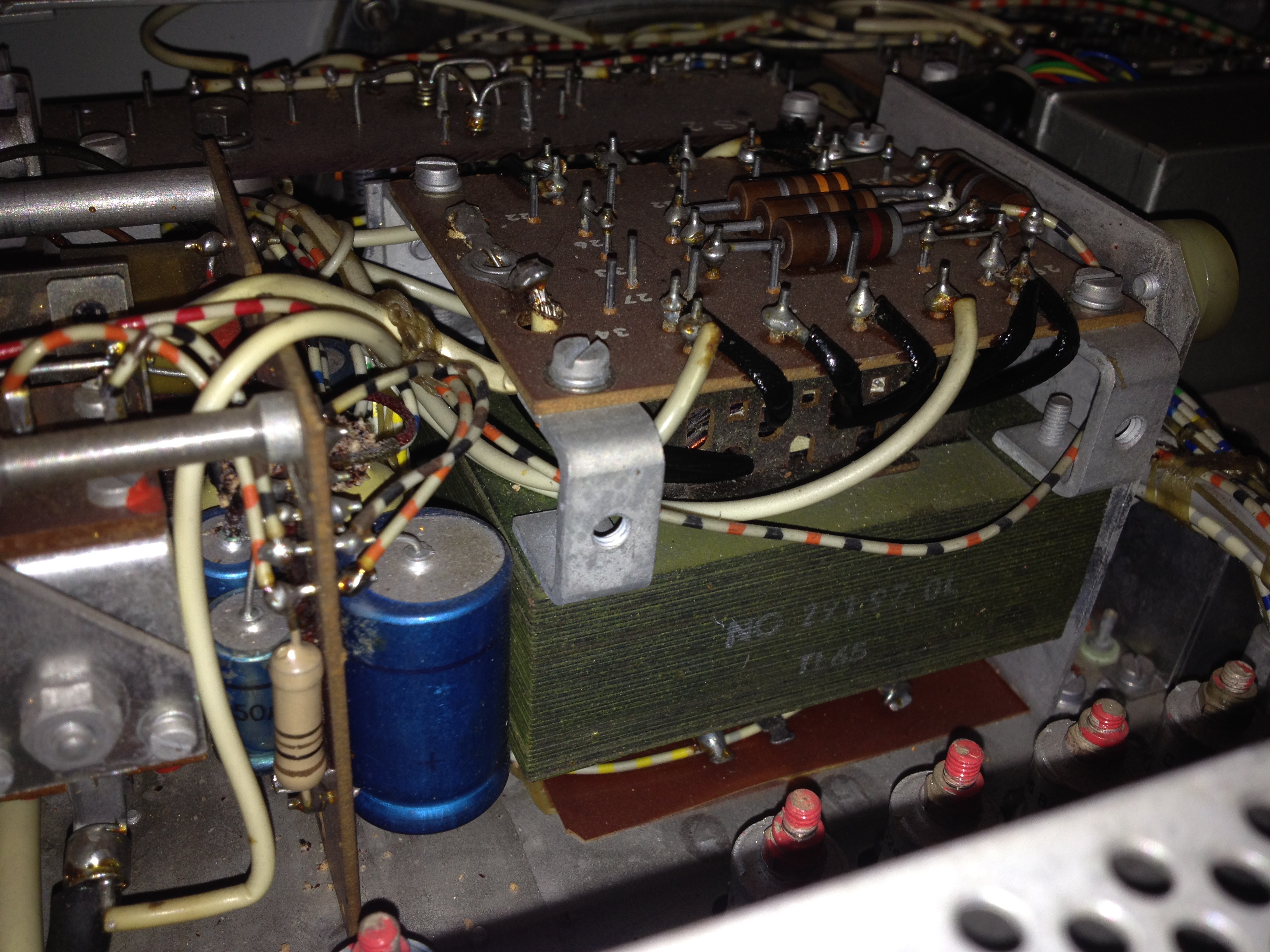
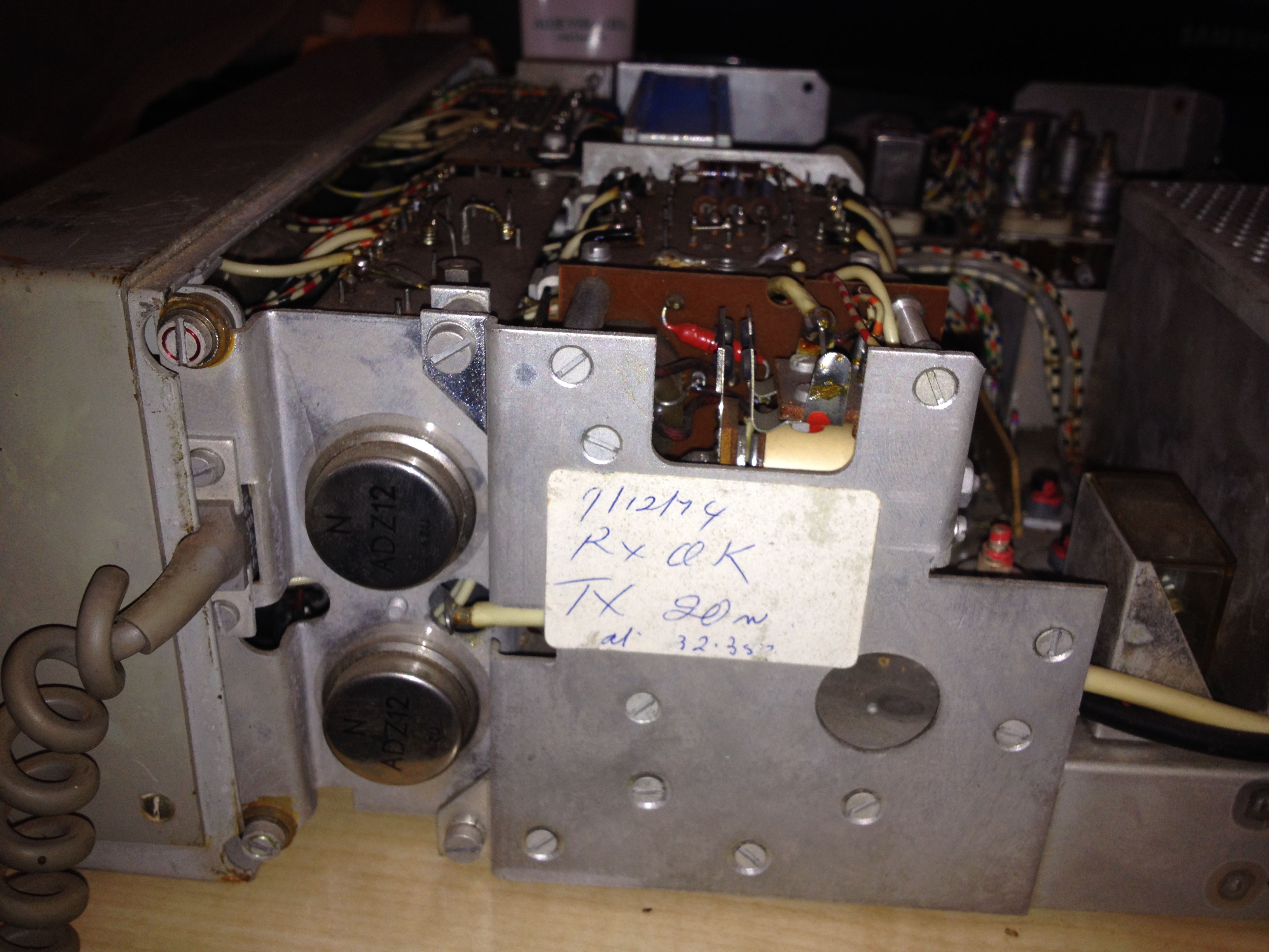
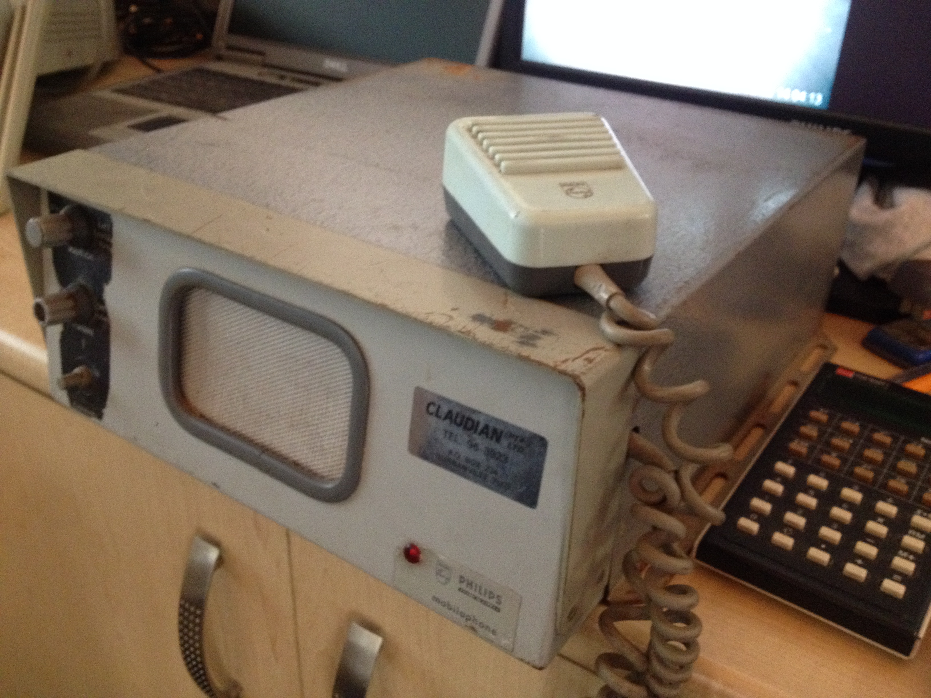
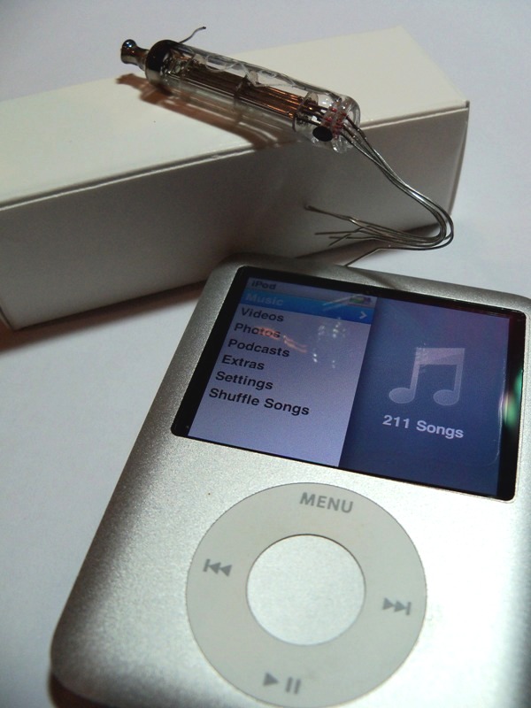
I recently managed too get my hands on this beauty. It works, but needs new capacitors.8/08/2014 Tube compliment EF50 ECH35 EF39 EBC33 EL33 DW4/350 The 1j17b is a miniature pentode that was used by the Russian military for their communication equipment. I was thinking of using two, along with a step-up DC-DC converter, for 60V HT, to make a small headphone amplifier. My iPod just doesn't have enough kick to drive a pair of big Sennheiser headphones. This tube is unusual in that it uses parallel rods instead of grids as control, screen and suppressor elements.
iPod and miniature vacuum tubes, the perfect combination
The Millett Hybrid Headphone Amplifier, BUF634 SMD version
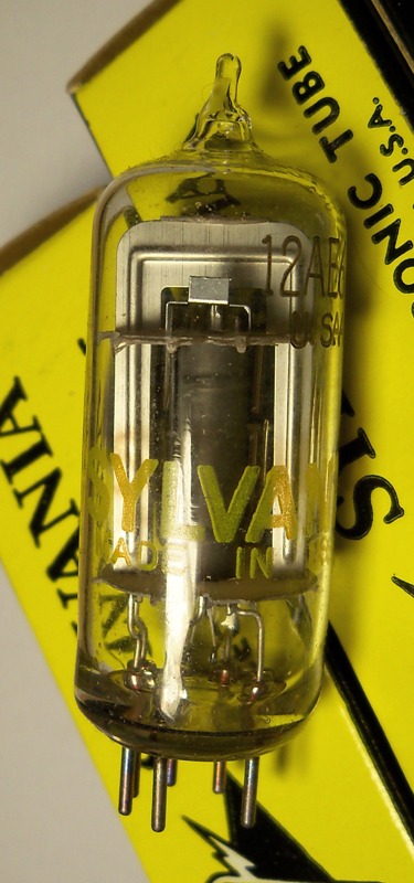
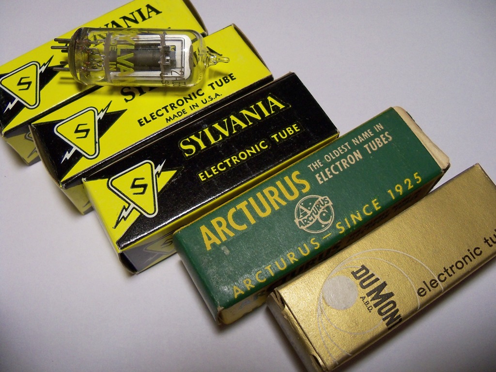
I recently (July 2010) bought some 12AE6A vacuum tubes on e-bay. Why? To built a Millett Hybrid amp of course. The Millett is a low voltage vacuum tube headphone amp. Gain is provided by two 12AE6A space charge tubes together with a semiconductor output stage to drive a low impedance load. This has the advantage of not needing an expensive output transformer. I almost exclusively listen to music on headphones, I love tubes and I'm nervous of high voltages so the Millett is perfect for me. I also managed to get free samples of the Burr-Brown BUF634 which is used in the output stage. The BUF634 is used to match the very high output impedance of the tubes to the low impedance of a pair of headphones. It has a gain of <1 and is only there to provide current to the load. The BUF634 is R80 each from RS Components! Score! The BUF634's are surface mount so I had to adapt the board in Eagle CAD.
Tweaked layout for SMD BUF634.The large pads for the BUF634 is to help with heat dissipation. They actually don't get hot. CLICK image to download EAGLE CAD file Thank you Gregory for double-checking my work! Millett boards etched by my good friend, Richard Smuts. The rest of the assembly I did myself.
The Super-Simple 12AU7 Hybrid Headphone amp
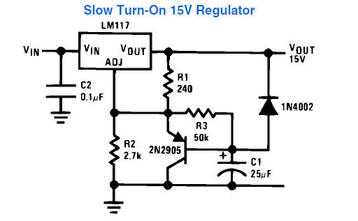
My improved PCB design with thicker tracks and neater layout. Version 2, 2011 There is also another hybrid tube design I found here. This design uses a single 12AU7 tube. This double triode makes it possible to have a stereo headphone amp with just one tube. Very simple to construct and devoid of high voltages, the 12AU7 (ECC82) / IRF510 Headphone Amp is a perfect beginners project. I redesigned the PCB artwork to make the layout neater and the tracks thicker. I no longer make PCBs for sale. I outsource those to a fabrication house. I only make prototypes myself. To power the Super-Simple 12AU7 headphone amplifier I recommend you use a linear power supply as opposed to a switched-mode power supply. Experience has shown switched-mode power supplies to introduce too much noise, audible as a pronounced hiss during quiet passages. This circuit will reward a clean, well regulated power supply. I also recommend you use a power supply of 12.6V. This is the rated voltage for the 12AU7 filaments. Any lower and I'm concerned one may not get sufficient electron emission. This amplifier draws ~598mA at 12.62V. The LM317s and IRF610s (in my case) get quite hot. I measured just under 50C with a temperature probe with the heatsinks on. I'm driving a pair of Sennheiser HD500s with mine. The sound is clear, detailed and punchy but never harsh. Overall the sound is very pleasant and open. It can easily drive my headphones to uncomfortable levels. I have it connected to a Monica2 NOS DAC. To eliminate switch-on pops I'm using a soft-start power supply based on the following from the National Semiconductor LM317 datasheet: Recently when assembling an amp I had a real problem with a humming/buzzing noise I couldn't trace. Turned out it was RFI from the DECT cordless phone base station on my desk. Moved it away and the amp went quiet.
The Power supply. Use R2 = 2180 Ω for 12.6 V.
Boards etched by my fabricator and good friend, Richard Smuts *All photographs are copyright AJ BREDEKAMP 2011 |
||||||||||||||||||||||||||||||||||||||||||||||||||||||||||||||||||||||||||||||||||||||||||||||||||||||||||||||||||||||||||||||||||||||||||||||||||||||||||||||||||||||||||||||||||||||||||||||||||||||||||||||||||||||||||||||||||||||||||||||||||||||||||||